Author: Addithive

  • Scaling Additive Manufacturing Production: Throughput, Yield and Factory Bottlenecks

    Scaling Additive Manufacturing Production: Throughput, Yield and Factory Bottlenecks

    Scaling additive manufacturing is not the same as buying a faster printer or adding more machines. Production scale is achieved when the complete system—orders, build preparation, printing, material handling, furnaces, machining, inspection and release—delivers accepted parts at the required rate, cost and quality.

    The factory bottleneck is rarely fixed. As print capacity rises, the constraint often moves to depowdering, debinding, sintering, heat treatment, support removal, machining or inspection.

    What high-volume AM really means

    “High volume” is application dependent. Thousands of personalized dental parts, hundreds of aerospace components and millions of small polymer parts represent very different production systems. A useful definition is the repeatable delivery of demand at target takt time with stable first-pass yield and controlled cost per accepted part.

    MetricWhy it matters
    Customer takt timeRequired interval between accepted finished parts
    Accepted parts per buildReal output after scrap and disposition
    End-to-end cycle timeTime from released order to part release
    First-pass yieldStability of the full process route
    Overall equipment effectivenessAvailability, performance and quality of constrained assets
    Cost per accepted partTrue economic outcome
    Queue time by operationLocation of hidden factory bottlenecks
    Engineering touch timeAbility to scale without proportional headcount

    The production-rate equation

    Printer speed is only one input. Approximate system output can be understood as:

    Accepted output = theoretical build capacity × availability × nesting efficiency × process yield × downstream yield.

    A machine with a short build time can still produce low output if setup is slow, nesting is poor, cooling is long, furnaces are full or inspection rejects parts. Conversely, a slower process can be economical when builds contain many parts and downstream operations are highly automated.

    Start with demand segmentation

    Do not mix every application into one production model. Segment demand by:

    • Process and machine family
    • Material and contamination controls
    • Part criticality and inspection route
    • Heat treatment, debinding or sintering recipe
    • Machining and finishing requirements
    • Order pattern: repeat, customized or engineering development
    • Required delivery lead time

    Stable repeat products should not compete for the same scheduling rules as development builds and one-off experiments.

    Capacity must be modeled across the complete route

    OperationCapacity driverCommon hidden loss
    Engineering reviewApplications per engineerRepeated manual quoting and manufacturability review
    Build preparationJobs released per plannerManual supports, file repair and approval loops
    PrintingBuild time and machine availabilitySetup, calibration, alarms, cooling and failed builds
    Powder/resin recoveryStations and laborManual handling, cleaning and material segregation
    Debinding/sinteringFurnace volume and cycle lengthSetter limits, shrinkage variation and batch incompatibility
    Heat treatment/HIPQualified furnace capacityLong queues and minimum economic batch size
    Support removalLabor, automation and geometryDamage, variable cycle time and ergonomic constraints
    MachiningFixture and spindle capacityDifficult datum transfer and interrupted surfaces
    InspectionTechnique time and equipment accessCT queues, manual report review and false calls
    Quality releaseData completeness and review timeDisconnected records and unresolved deviations

    Process-specific scaling models

    Polymer powder bed fusion

    Technologies such as polymer laser sintering and Multi Jet Fusion can pack many parts into a build without attached supports. Scale depends on nesting density, powder refresh, cooling, breakout, blasting, dyeing and dimensional consistency. A printer farm without automated powder and finishing flow can create large manual queues.

    Vat photopolymerization

    Projection and masked-light systems can expose a complete layer at once, but total throughput depends on part height, peel or separation mechanics, washing, drying, support removal and post-curing. Resin qualification and cleaning capacity become important at scale.

    Metal powder bed fusion

    Multi-laser platforms can increase exposure capacity, but the factory must also scale powder handling, build-plate logistics, stress relief, wire EDM, support removal, machining and NDT. More lasers do not automatically produce proportionally more accepted parts.

    Metal binder jetting

    Printing can be rapid and support-free, but green-part handling, depowdering, debinding, setter design and sintering control define production economics. Furnace capacity and shrinkage variation are often the dominant constraints.

    Directed energy deposition

    DED can deposit material rapidly, especially for large wire-fed systems. Scale depends on path development, thermal control, machine occupancy, heat treatment, machining and inspection. Gross deposition rate is not final-part takt time.

    Nesting and product mix

    AM machines often process multiple parts in one batch. This creates opportunities and risks:

    • Higher nesting density can reduce unit machine cost.
    • Mixing part types can complicate traceability, heat treatment and release.
    • A single failed feature or alarm can place an entire build at risk.
    • Tall parts can determine build time even when the rest of the volume is underused.
    • Different due dates can create scheduling conflict inside the same build.
    • Shared builds require clear location, serial-number and material-coupon mapping.

    Nesting optimization should balance cost, delivery risk, thermal interaction and quality—not only fill percentage.

    Automation priorities

    Automation creates the most value when applied to stable, repetitive work. High-impact opportunities include:

    • Automated order intake and manufacturability screening
    • Template-based orientation, supports and build release
    • Material identification and genealogy
    • Automated powder or resin handling
    • Robotic part recovery and support removal
    • Standard fixtures and probing for machining
    • Automated metrology and report generation
    • MES routing, electronic travelers and release checks
    • Analytics for yield, queues and preventive maintenance

    Automating an unstable process makes variation faster. Standardize and measure before automating.

    First-pass yield is the scaling multiplier

    A small yield loss compounds across multiple operations. For example, a build route with 95% yield at printing, 95% at post-processing and 95% at final inspection produces only about 86% overall yield before other losses.

    Yield improvement can therefore create more effective capacity than adding another printer. Track defects by operation and distinguish:

    • Build failure
    • Dimensional nonconformance
    • Material-property failure
    • Post-processing damage
    • Machining scrap
    • NDT rejection
    • Documentation or traceability failure

    Factory layout and material flow

    Production layout should minimize uncontrolled movement of feedstock, parts and data. Consider:

    • Separation of incompatible or reactive materials
    • One-way flow for powder, green parts and finished hardware
    • Safe transfer to furnaces and depowdering stations
    • Space for quarantine and nonconforming material
    • Environmental controls and housekeeping
    • Ergonomics for repetitive recovery and finishing work
    • Digital work instructions at the point of use
    • Expansion space around the real bottleneck, not only printers

    Qualification at scale

    Scaling introduces new equivalency questions:

    • Can production move between machines of the same model?
    • How are multiple lasers, nozzles or print heads compared?
    • Can a build be transferred to another site or supplier?
    • What software, firmware or parameter changes require revalidation?
    • How is furnace and post-process equivalency established?
    • Which monitoring or inspection data supports reduced testing?

    The organization should define equivalency and change-control rules before capacity expansion, not after the original machine becomes overloaded.

    Economics of capacity expansion

    Before purchasing another machine, compare four options:

    1. Improve yield: remove recurring scrap and rework.
    2. Reduce setup and queue time: standardize builds and balance downstream flow.
    3. Increase nesting or batch efficiency: improve usable output per cycle.
    4. Add or outsource capacity: expand only when the constrained step remains capacity-limited after improvement.

    Printer acquisition should include the proportional investment needed in material handling, furnaces, machining, inspection, people, software and floor space.

    Production-readiness checklist

    1. Recurring demand and product mix are visible.
    2. Released designs and build configurations are controlled.
    3. Feedstock and material genealogy are scalable.
    4. The complete capacity model identifies the current constraint.
    5. First-pass yield is stable and causes of loss are understood.
    6. Post-processing and inspection can meet forecast demand.
    7. Machine, furnace and site equivalency rules are defined.
    8. MES, travelers and part genealogy support the volume.
    9. Operators, engineers and quality staff are trained for all shifts.
    10. Cost per accepted part meets the business case at realistic utilization.

    Conclusion

    High-volume additive manufacturing is a factory-system problem. Scale comes from balanced capacity, repeatable applications, high first-pass yield, controlled data and efficient downstream flow. The correct investment is the one that increases accepted-part throughput at the current constraint—not automatically another printer.

    Related Addithive resources: AM Adoption Roadmap · Binder Jetting Economics

    AM Bottleneck Brief

    Scale the complete route—not only printer capacity.

    Get the free Industrial AM Bottleneck Atlas and a weekly evidence-led brief on throughput, yield, downstream capacity and exposed companies.

    Confirm your email after subscribing. Research mapping only.
    References and further reading

  • Wire-Fed Electron Beam Directed Energy Deposition: Process, Applications and Limits

    Wire-Fed Electron Beam Directed Energy Deposition: Process, Applications and Limits

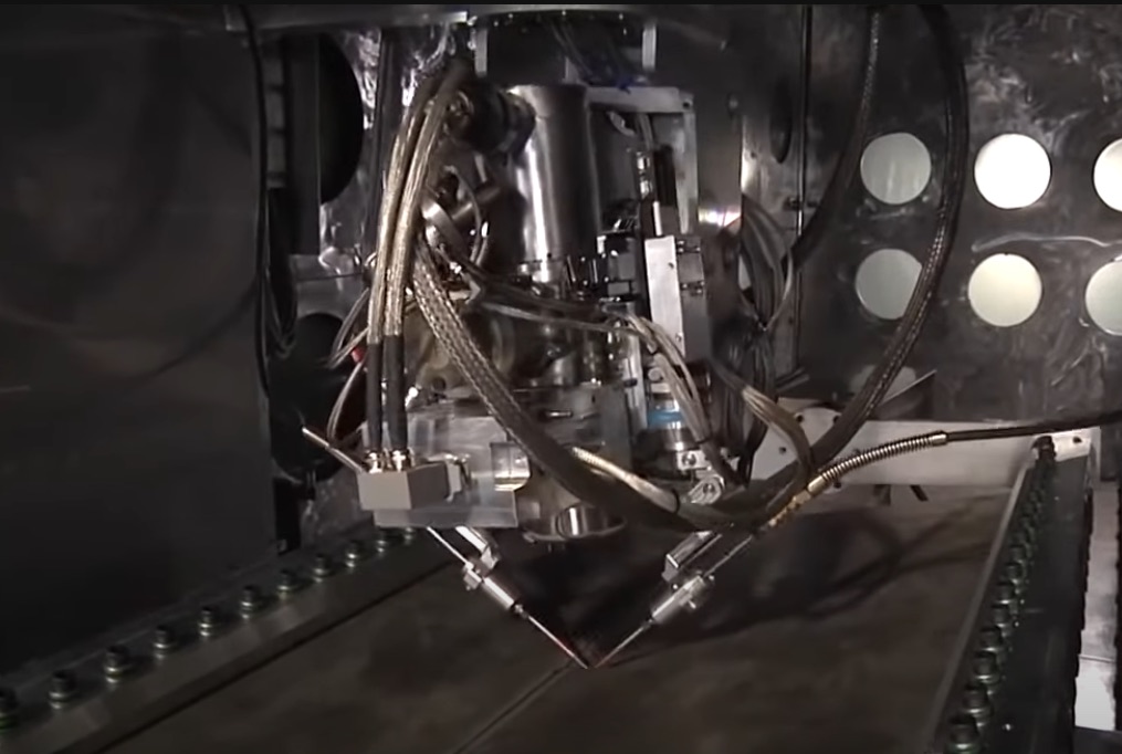
    Wire-fed electron beam additive manufacturing is a directed energy deposition process in which an electron beam creates a melt pool and metallic wire is fed directly into it. The standardized process description is DED-EB/M using wire feedstock. “EBAM” is also widely used, but it is a trademarked commercial term associated with Sciaky.

    This is not electron beam powder bed fusion. Wire-fed DED-EB is built for large near-net shapes, repair and high deposition rates—not fine powder-bed resolution.

    How wire-fed DED-EB works

    1. Digital process planning: A CAD model is converted into deposition paths, layer strategy, machine motion and wire-feed instructions.
    2. Substrate preparation: The build plate, preform or repair component is cleaned, positioned and qualified for deposition.
    3. Vacuum generation: The work chamber is evacuated to permit stable electron-beam operation and reduce oxidation of reactive alloys.
    4. Melt-pool creation: The focused electron beam melts a controlled area of the substrate or previous layer.
    5. Wire deposition: Wire enters the melt pool while the beam, part or deposition head follows the programmed path.
    6. Layer or bead stacking: Beads are overlapped to create walls, features or large near-net preforms.
    7. Monitoring and correction: Beam power, wire feed, travel speed and melt-pool condition may be monitored and adjusted by the machine control system.
    8. Post-processing: The deposited shape is heat treated, inspected and machined to final geometry as required.

    Process classification

    ASTM F3187 defines directed energy deposition as a process in which focused thermal energy fuses material as it is being deposited. DED can use laser, electron-beam or arc energy and can use wire or powder feedstock. Wire-fed electron-beam systems are one branch of this larger process family.

    ProcessEnergy sourceTypical feedstockEnvironmentBest-known use
    DED-EB/MElectron beamWireVacuumLarge near-net preforms in high-value reactive metals
    DED-LB/MLaserPowder or wireInert shielding or controlled enclosureRepair, coatings, features and multi-axis deposition
    DED-Arc/MArc plasmaWireShielding gas or local enclosureLarge structures and high-rate deposition
    PBF-EB/MElectron beamPowder bedVacuumComplex smaller parts, implants and selected aerospace hardware

    Why wire feedstock matters

    Wire is generally easier to handle than fine reactive powder and can provide high material-delivery rates. It is available in established welding-alloy specifications for many metals, although AM production still requires control of chemistry, diameter, cleanliness, cast, helix, spool identity and storage.

    Wire-fed deposition converts stock directly into a near-net shape, but it does not eliminate waste. Start/stop regions, run-on and run-off features, machining allowance, rejected builds and removed substrate material remain part of the yield calculation.

    Main advantages

    High deposition rate

    Commercial systems can deposit several kilograms per hour, with rate strongly dependent on alloy, geometry, quality requirements and machine configuration. Gross deposition rate should not be confused with finished-part throughput. Vacuum cycle, cooling, inspection, heat treatment and machining can dominate total lead time.

    Large build envelope

    DED-EB can produce structures far larger than typical powder-bed machines. The practical limit is set by chamber size, motion system, thermal control, wire access and the ability to machine and inspect the deposited shape.

    High-value material savings

    The strongest economic case often occurs when a large titanium, nickel, tantalum or other expensive-alloy part would otherwise be machined from a very large forging or billet. A near-net DED preform can reduce buy-to-fly ratio and shorten raw-material lead time.

    Repair and feature addition

    Because feedstock is delivered into a local melt pool, DED can add material to existing components or preforms. Repair acceptance requires a defined damage-removal route, substrate condition, interface design, heat treatment and inspection plan.

    Main limitations

    • Low geometric resolution: Bead width and layer height are much larger than powder-bed features.
    • Machining dependency: Critical surfaces, datums, holes and interfaces are normally finish machined.
    • Thermal distortion: Large heat input and long deposition paths can cause warping and residual stress.
    • Bead stability: Wire position, transfer behavior, melt-pool size and path transitions affect consistency.
    • Vacuum infrastructure: Chamber size, pump-down time, seals and maintenance affect cost and availability.
    • Limited access: The beam and wire must reach the deposition location without collision or shadowing.
    • Qualification burden: Large components are expensive to test destructively and difficult to inspect volumetrically.
    • Microstructure variation: Thermal history can vary across thick intersections, starts, stops and long builds.

    Design for wire-fed DED-EB

    • Design near-net, not net-shape. Define machining allowance from process capability and distortion evidence.
    • Use accessible geometry. Ensure the beam, wire and motion system can reach each feature.
    • Control section transitions. Abrupt mass changes create thermal accumulation and path-planning difficulty.
    • Plan deposition sequence. Bead order, direction and dwell time influence distortion and microstructure.
    • Create machining datums. Include robust features for setup, probing and final coordinate transfer.
    • Include run-on and run-off strategy. Starts and stops may require sacrificial material.
    • Design for inspection. Avoid large uninspectable volumes unless process evidence and risk analysis justify them.
    • Consider hybrid substrates. Deposit only where AM creates value and retain forged, plate or machined material elsewhere.

    ISO/ASTM 52922, a design standard for metal DED, was still under development in 2026. ASTM F3413 provides existing design guidance for DED and should be interpreted together with application-specific engineering requirements.

    Materials

    Wire-fed DED-EB is especially attractive for reactive or high-value alloys that benefit from vacuum processing:

    • Titanium and titanium alloys
    • Nickel-based superalloys
    • Tantalum, niobium and selected refractory metals
    • Selected steels and other weldable alloys

    Weldability is a useful starting point but is not sufficient. The route must control dilution, segregation, solidification cracking, phase transformation, chemistry pickup and heat-treatment response.

    Multi-wire and graded materials

    Some systems can use dual wire feeds to increase deposition or vary chemistry. This creates potential for graded composition and custom alloy development, but it also introduces major control questions:

    • How are the two feed rates calibrated and synchronized?
    • Is mixing within the melt pool uniform and repeatable?
    • Can local chemistry be verified throughout the part?
    • Do intermediate compositions form brittle phases?
    • How will the material be specified, heat treated and qualified?

    Multi-material capability should therefore be treated as a material-development program, not a routine printer option.

    Process monitoring and control

    Key variables include beam power, focus, travel speed, wire-feed rate, wire position, melt-pool geometry, layer height and machine motion. Commercial platforms may use cameras or thermal sensing to adjust deposition conditions.

    Closed-loop control can reduce variation, but it does not automatically prove internal quality. Sensor calibration, latency, field of view, data retention and correlation with physical defects remain essential.

    Typical imperfections

    Imperfection or conditionPotential contributors
    Lack of fusionLow energy, poor bead overlap, wire misalignment or contaminated interface
    PorosityWire condition, unstable transfer, entrapped gas or melt-pool turbulence
    CrackingAlloy susceptibility, thermal gradient, restraint and composition changes
    Bead-shape variationWire feed, beam power, travel speed, surface condition and local heat buildup
    DistortionDeposition sequence, substrate restraint, heat input and cooling
    Interface defectsOxide, contamination, insufficient dilution or inadequate surface preparation
    Chemistry variationEvaporation, feedstock variation, cross-contamination or multi-wire imbalance

    ASTM work on a standardized DED imperfection classification was still underway in 2026. Until acceptance frameworks mature, the inspection plan should be based on credible process-specific failure modes and representative demonstration hardware.

    Post-processing and inspection

    • Stress relief, solution treatment, aging or HIP as required
    • Removal from the substrate or retention as a hybrid component
    • Rough and finish machining
    • Surface finishing and cleaning
    • Dimensional inspection
    • Surface and volumetric NDT selected for geometry and defect orientation
    • Material testing from qualified witness locations

    Very large parts can exceed practical CT capacity. Ultrasonic, radiographic, surface and local destructive methods may need to be combined with process qualification and monitoring.

    Applications

    • Aerospace structures: large titanium preforms, tanks, frames and structural features
    • Defense: low-volume, long-lead, high-value metal hardware
    • Energy: large nickel, refractory or specialized-alloy components
    • Repair and remanufacturing: restoration or addition of high-value features
    • Material development: controlled composition experiments using multiple wires

    Economics

    The economic comparison should be against the complete conventional route, often a large forging plus extensive machining. Include:

    • Wire and substrate cost
    • Vacuum and deposition cycle
    • Engineering and path development
    • Build failures and qualification hardware
    • Heat treatment and HIP
    • Machining time and removed material
    • Inspection and documentation
    • Raw-material and tooling lead-time reduction

    DED-EB is strongest where the alternative has a very high buy-to-fly ratio, long forging lead time, low production volume and expensive alloy. It is weak for small precision components that can be produced efficiently by powder bed, casting or machining.

    Selection checklist

    1. Is the part large enough and valuable enough to justify DED?
    2. Can the geometry be created as accessible overlapping beads?
    3. Is suitable wire available with controlled quality and supply?
    4. Can the deposited material be heat treated and qualified?
    5. Is sufficient machining stock included?
    6. Can the complete volume and interfaces be inspected?
    7. Does the facility have vacuum, handling and safety capability?
    8. Does accepted-part cost beat forging, fabrication or alternative DED routes?

    Conclusion

    Wire-fed electron beam DED is a high-rate near-net-shape process for large, high-value metal components. Its advantage comes from combining vacuum processing, wire feedstock and large-scale deposition. Its limitations—coarse geometry, thermal management, machining and qualification—must be included from the first design decision.

    Related Addithive resources: Electron Beam Powder Bed Fusion · Wire Arc Additive Manufacturing

    References and further reading

  • The Seven Additive Manufacturing Process Categories: Methods, Materials and Selection

    The Seven Additive Manufacturing Process Categories: Methods, Materials and Selection

    Additive manufacturing technologies are often described by commercial names such as FDM, SLS, SLA, DMLS, PolyJet or WAAM. These names are useful, but they can mix trademarks, historical terms and process physics. A clearer starting point is the seven process categories used by ISO/ASTM terminology.

    Choose an additive manufacturing process by how material is delivered, consolidated and supported—not by the popularity of a machine brand.

    ISO/ASTM 52900:2021 remains the current confirmed international vocabulary standard for additive manufacturing. It defines AM as creating physical 3D geometry through successive addition of material and organizes the field into standardized process categories.

    The seven standard AM process categories

    Process categoryHow the part is formedCommon feedstockTypical applications
    Vat photopolymerizationLight selectively cures liquid photopolymer in a vatPhotopolymer resin or ceramic-filled slurryDental devices, models, patterns and fine polymer parts
    Material extrusionMaterial is selectively dispensed through a nozzle or orificeThermoplastic filament, pellets, paste, concrete or bioinkPrototypes, tooling, large-format parts and construction
    Powder bed fusionThermal energy selectively fuses regions of a powder bedPolymer, metal or selected ceramic powderFunctional polymer parts, metal components and implants
    Binder jettingLiquid binder selectively joins particles in a powder bedMetal, ceramic, sand, gypsum or other particulate materialSand molds, metal parts, ceramics and visual models
    Material jettingDroplets of build material are selectively depositedPhotopolymer, wax, nanoparticle suspension or functional inkDetailed models, casting patterns and multi-material parts
    Directed energy depositionFocused energy melts material as it is depositedMetal powder or wireRepair, feature addition and large near-net metal parts
    Sheet laminationSheets are bonded and shaped layer by layerPaper, polymer, metal foil or composite sheetModels, embedded structures and selected metal components

    1. Vat photopolymerization

    Vat photopolymerization uses light to selectively solidify a liquid resin. The category includes several light-delivery and layer-separation approaches:

    • Laser SLA: a focused laser scans the layer.
    • DLP: a projector exposes a complete layer or projected region.
    • MSLA/LCD: an LCD mask shapes light from an underlying source.
    • Continuous-interface methods: reduce discrete peel interruptions through a controlled inhibition or separation zone.

    Strengths: fine detail, smooth surfaces, dental and medical material ecosystems, full-layer exposure on projection systems and broad visual-model capability.

    Constraints: uncured-resin handling, washing, drying, post-curing, support marks, long-term polymer aging and indication-specific material validation.

    Read the detailed vat photopolymerization guide.

    2. Material extrusion

    Material extrusion selectively dispenses material through a nozzle. The most familiar route melts thermoplastic filament, but the category is much broader.

    • Filament extrusion: commonly called FFF; FDM is a Stratasys-associated trademarked term.
    • Pellet extrusion: uses polymer granules for higher material flow and large-format systems.
    • Paste extrusion: deposits ceramics, food, energetic materials, silicones or other viscous formulations.
    • Concrete extrusion: deposits pumpable cementitious material for construction elements.
    • Extrusion bioprinting: deposits cell-containing or biomaterial formulations for research.

    Strengths: accessible equipment, wide material forms, low feedstock cost, large build sizes and straightforward multi-material concepts.

    Constraints: bead-scale resolution, anisotropy, voids, interlayer bonding, warpage, support needs and variable surface quality.

    3. Powder bed fusion

    Powder bed fusion spreads a layer of powder and selectively fuses regions using thermal energy. The unused powder supports surrounding geometry, although metal systems often still need supports for heat transfer, anchoring and distortion control.

    Polymer PBF

    Selective laser sintering is widely used for nylon and thermoplastic elastomer components. Other commercial platforms use alternative heating or fusing-agent strategies while remaining within powder-bed-based polymer production concepts.

    Laser metal PBF

    Laser powder bed fusion of metal is also described by commercial or historical names such as SLM and DMLS. The standardized process description is clearer: PBF-LB/M, powder bed fusion using a laser beam for metallic material.

    Electron-beam metal PBF

    PBF-EB/M uses an electron beam in vacuum and typically maintains an elevated powder-bed temperature. It is distinct from wire-fed electron-beam directed energy deposition.

    Strengths: complex geometry, functional polymer production, dense metal parts, strong aerospace and medical ecosystems.

    Constraints: powder safety and genealogy, thermal distortion, supports, surface condition, build size, machine qualification and post-processing.

    Related guides: LPBF terminology and electron-beam PBF.

    4. Binder jetting

    Binder jetting selectively deposits a liquid binder onto a powder bed. The printed object is usually a weak green part or mold that requires additional processing.

    • Sand binder jetting: produces molds and cores for metal casting.
    • Metal binder jetting: prints a green part followed by depowdering, debinding and sintering.
    • Ceramic binder jetting: creates green ceramic shapes requiring thermal processing or infiltration.
    • Color model printing: uses colored binder with suitable powder systems for visual models.

    Strengths: rapid area-based printing, support-free powder-bed geometry, high nesting density and useful foundry applications.

    Constraints: fragile green parts, depowdering, binder removal, furnace capacity, shrinkage, distortion and final density.

    Read the binder jetting guide.

    5. Material jetting

    Material jetting deposits droplets of build material. The deposited material can be cured by light, cooled from a molten state or processed through another consolidation step.

    • Photopolymer material jetting: produces detailed multi-material and multi-color polymer models.
    • Wax jetting: creates precision casting patterns.
    • Nanoparticle or suspension jetting: deposits material-containing droplets followed by drying, curing or sintering.
    • Functional ink deposition: overlaps with printed and additively manufactured electronics.

    Strengths: fine visual detail, color, controlled droplet placement and multi-material capability.

    Constraints: material cost, support removal, UV and thermal aging, nozzle maintenance and limited structural-material options on many platforms.

    6. Directed energy deposition

    Directed energy deposition delivers material into a focused heat source. Unlike powder bed fusion, feedstock enters only where material is being deposited.

    DED routeEnergy sourceFeedstockTypical use
    Laser DEDLaserPowder or wireRepair, coatings and feature addition
    Arc DED / WAAMElectric arcWireLarge structures and high-rate near-net deposition
    Electron-beam DEDElectron beamUsually wireLarge reactive-metal preforms under vacuum

    Strengths: repair, large build envelope, high deposition rate, hybrid manufacturing and low buy-to-fly potential.

    Constraints: coarse feature resolution, thermal distortion, bead stability, substantial machining and difficult inspection of large volumes.

    Related guides: wire arc AM and wire-fed electron-beam DED.

    7. Sheet lamination

    Sheet lamination bonds layers of sheet material and shapes them into the final geometry. Major routes include:

    • Laminated object manufacturing: cuts and bonds paper, polymer or composite sheets.
    • Ultrasonic additive manufacturing: bonds metal foils using ultrasonic energy, often with intermediate machining.
    • Composite sheet lamination: stacks and bonds reinforced sheets or tapes.

    Strengths: relatively low thermal exposure in ultrasonic metal routes, embedded sensors or channels, multi-material sheet combinations and rapid model production.

    Constraints: interlayer bonding, geometric access, removal of surrounding material, limited adoption and process-specific design rules.

    Processes often confused with the seven categories

    TermHow to classify it
    Hybrid manufacturingA production system combining AM with machining or another process; the AM step still belongs to one of the seven categories
    BioprintingAn application domain using extrusion, material jetting, vat or other deposition principles
    Construction 3D printingUsually material extrusion, although printed formwork and metal routes can use other categories
    Additively manufactured electronicsAn application field using material jetting, extrusion, aerosol deposition and hybrid methods
    Cold spray additive manufacturingCommonly treated within directed-energy-deposition-related industrial frameworks, although consolidation occurs through high-velocity solid-state impact rather than melting
    Voxel printingA design and material-control concept rather than a separate fundamental process category
    4D printingPrinted objects designed to change over time under a stimulus; not a separate AM process category

    How to select the right process

    1. Define the application. Prototype, tool, implant, flight part and visual model require different evidence.
    2. Start with the material. Confirm that a qualified feedstock and post-processing route exist.
    3. Set the geometry envelope. Include build size, minimum walls, channels, overhangs and machining access.
    4. Define property requirements. Strength, fatigue, temperature, chemical resistance and aging may eliminate processes early.
    5. Map post-processing. Supports, cleaning, heat treatment, HIP, debinding, sintering and finishing can determine feasibility.
    6. Plan inspection. Complex internal features need credible measurement and defect-detection methods.
    7. Calculate accepted-part economics. Include yield, labor, furnaces, machining and quality—not only print time.
    8. Evaluate scale. Determine whether takt time and downstream capacity meet demand.
    9. Check qualification maturity. Standards, supplier capability and material data vary by process.
    10. Compare hybrid alternatives. The best solution may print only the difficult feature and use conventional processes elsewhere.

    Quick process-selection matrix

    RequirementProcesses commonly considered first
    Fine polymer detailVat photopolymerization or material jetting
    Durable support-free polymer productionPolymer powder bed fusion
    Complex dense metal partsMetal powder bed fusion
    Large metal near-net shapesDirected energy deposition
    High-density metal batch productionMetal binder jetting where sintering and economics are proven
    Low-cost desktop prototypesMaterial extrusion
    Sand molds and coresBinder jetting
    Multi-color visual modelsMaterial jetting or selected binder-jet systems
    Embedded materials or sensors in metal foilUltrasonic sheet lamination
    Repair or local feature additionDirected energy deposition

    Conclusion

    The additive manufacturing universe is easier to understand when commercial names are mapped to seven standardized process categories. Each category solves a different material-delivery and consolidation problem. Process selection should begin with application requirements and include the complete downstream route, qualification burden and cost per accepted part.

    Related Addithive resources: Introduction to Additive Manufacturing · Metal AM Process Selection · History of Additive Manufacturing

    Reference

  • Dental Additive Manufacturing: Digital Workflow, Materials and Production Control

    Dental Additive Manufacturing: Digital Workflow, Materials and Production Control

    Dental additive manufacturing is one of the most mature examples of mass customization. The real advantage comes from connecting patient data, treatment design, printing, washing or sintering, inspection and clinical delivery in a controlled digital workflow.

    A dental resin is not approved for every dental use. The exact material, printer, wash, post-cure and intended indication must match the validated device route.

    The dental digital workflow

    1. Capture patient geometry: Intraoral scan, desktop scan or conventional impression converted to digital data.
    2. Plan treatment or restoration: Teeth, gingiva, implant position and occlusion are reviewed in dental CAD software.
    3. Design the device: Model, guide, splint, denture, temporary restoration or metal framework is created within approved rules.
    4. Prepare the build: Orientation, supports, nesting, layer strategy and material profile are released.
    5. Print: The device or manufacturing model is produced on a qualified machine.
    6. Post-process: Wash, dry, post-cure, support removal, sintering, polishing or finishing are completed as required.
    7. Inspect: Identity, dimensions, fit, surface and device-specific requirements are verified.
    8. Clinical delivery: The dentist checks fit and use under the applicable treatment plan.
    9. Retain records: Scan, design, material lot, printer, build, post-cure and release data remain linked.

    What is actually 3D printed in dentistry?

    ApplicationTypical manufacturing routeKey control
    Orthodontic modelsVat photopolymerization followed by washing and curingDimensional accuracy and production throughput
    Clear alignersTraditionally thermoformed over printed models; direct printing is an emerging validated route for specific systemsTreatment plan, material indication, thickness and final cure
    Surgical guidesDental resin printing, washing, curing and sterilizationGuide fit, sleeve position and sterilization compatibility
    Splints and night guardsDirect resin printing or conventional fabrication from a digital designBiocompatibility, occlusion, wear and post-cure
    Denture bases and teethPrinted components assembled or printed using device-specific systemsBonding, fit, fracture resistance and intended-use clearance
    Temporary crowns and bridgesDirect printing with indication-specific resinMarginal fit, cure, strength and intraoral exposure
    Permanent restorationsSelected printable resins or ceramics where specifically validatedLong-term wear, color, strength and regulatory status
    Metal frameworksLaser powder bed fusion of cobalt-chromium or titanium, then heat treatment and finishingFit, surface, support removal and material properties
    Castable patternsPrinted resin pattern followed by investment castingBurnout behavior and casting accuracy
    Anatomical modelsPolymer printing from imaging dataSegmentation and dimensional fidelity

    Aligner production: model-based vs direct printing

    Most established aligner production has used a two-step route: print a sequence of dental models and thermoform polymer sheets over them. This scales well but creates a model for every treatment stage.

    Directly printed aligners can remove the model and thermoforming steps, but the route is not simply “print any transparent resin.” It requires a material and process validated for direct intraoral use, controlled thickness, mechanical response, washing, post-curing and treatment performance.

    Vat photopolymerization in dental production

    Laser SLA, DLP and MSLA systems all cure liquid resin, but their optical architecture, pixel or spot behavior and separation mechanics differ. Dental production should be validated at the system level:

    • Printer and firmware version
    • Resin name, lot and shelf life
    • Layer thickness and exposure profile
    • Build orientation and support strategy
    • Wash solvent, concentration and cycle
    • Drying before cure
    • Post-cure wavelength, time and temperature
    • Support removal and finishing
    • Final inspection and release

    See Addithive’s vat photopolymerization guide for SLA, DLP, MSLA, washing, curing and resin-safety fundamentals.

    Why washing and post-curing are critical

    A part leaving a resin printer usually contains uncured surface resin and has not reached its final properties. Inadequate washing or post-curing can affect fit, strength, surface tack, residual chemistry, color and biocompatibility.

    • Do not mix validated wash and cure parameters between different materials.
    • Track solvent contamination and replace it using defined limits.
    • Allow parts to dry before post-curing.
    • Space devices so light and heat reach all required surfaces.
    • Verify cure-unit output and maintenance.
    • Inspect internal channels and guide holes for retained resin.
    • Use final-condition parts for performance evaluation.

    Dental material indications are specific

    The FDA notes that dental materials can be cleared for specific intended uses, such as denture bases, retainers, night guards, crowns or bridges. Clearance for one indication does not automatically allow the same material to be used for another device.

    Check the current manufacturer instructions and applicable regulatory status for the exact region. Terms such as “dental resin,” “biocompatible” or “medical grade” are not sufficient by themselves.

    Metal additive manufacturing in dentistry

    Metal powder bed fusion can manufacture cobalt-chromium and titanium frameworks, implant-related components and other dental hardware. The production route can include:

    • Powder and machine qualification
    • Support and build-layout control
    • Stress relief or other thermal processing
    • Part separation and support removal
    • Machining of interfaces
    • Polishing and cleaning
    • Dimensional and material verification

    As-built metal surfaces are not automatically suitable for every oral-contact or fatigue application. Surface and cleaning requirements must be defined for the finished device.

    Chairside, dental laboratory or industrial production?

    ModelStrengthOperational challenge
    ChairsideFast clinical iteration and fewer logistics stepsLimited staff, quality-system burden and equipment maintenance
    Dental laboratorySpecialized design and broad device capabilityOrder mix, traceability and customer-specific requirements
    Centralized industrial productionAutomation, scale, validated cells and material expertiseLogistics, turnaround and dependence on digital-data quality

    The correct model depends on case volume, device risk, required turnaround, staff competence and the ability to control the complete post-processing route.

    Quality-control checklist

    1. Confirm patient and order identity before design and print release.
    2. Validate the scanner, software and design workflow.
    3. Use the approved printer–material–profile combination.
    4. Track resin or powder lot, storage and reuse.
    5. Control orientation, supports and nesting.
    6. Record washing, drying and post-curing.
    7. Inspect fit-critical and guide-critical dimensions.
    8. Verify cleaning and sterilization where required.
    9. Manage failed builds, remakes and nonconformances.
    10. Retain traceability from scan to clinical delivery.

    Common misconceptions

    • “All aligners are directly printed.” Most established production has used printed models and thermoforming.
    • “Any biocompatible resin can be used intraorally.” Intended use and validated processing are specific.
    • “Higher pixel resolution guarantees better fit.” Optics, resin, compensation, orientation and post-cure all affect accuracy.
    • “Printing eliminates dental technicians.” Digital design, finishing, inspection and clinical judgment remain essential.
    • “Every crown or implant can now be printed.” Material and device maturity vary substantially by application.

    Conclusion

    Dental AM succeeds because it converts unique patient geometry into a repeatable digital-production system. The competitive advantage is not the printer alone; it is the validated connection between scanning, design, material, post-processing, inspection and clinical use.

    Related Addithive resources: Medical Additive Manufacturing · Straumann Dental AM Profile · Dentsply Sirona Primeprint Profile

    References and further reading

  • Binder Jetting: Process, Materials, Economics and Industry Platforms

    Binder Jetting: Process, Materials, Economics and Industry Platforms

    Binder jetting selectively deposits a liquid binder onto a powder bed to create a “green” part. The printing step is relatively fast and does not use a laser to melt each voxel. But for metal and many ceramic applications, printing is only the beginning: curing, depowdering, debinding and sintering determine the final geometry and properties.

    The central binder-jetting challenge is not print speed. It is controlling the complete print-to-sinter route with acceptable shrinkage, distortion, density and yield.

    How binder jetting works

    1. A recoater spreads a controlled layer of powder.
    2. An inkjet printhead selectively deposits binder according to the sliced geometry.
    3. The build platform moves and the process repeats.
    4. The powder bed is cured or dried to provide handling strength.
    5. Green parts are removed from the surrounding powder and cleaned.
    6. For metal or ceramic routes, the binder is removed and the part is sintered.
    7. Finishing, heat treatment, machining and inspection are applied as required.

    Sand molds and cores follow a different downstream route: the printed sand tool is cleaned and used directly in a casting process rather than sintered into a dense metal component.

    Schematic of the binder jetting process

    Three distinct binder-jetting markets

    ApplicationPrinted materialWhat the printed object becomesMain value driver
    Metal binder jettingMetal powder plus binderA sintered metal componentBatch productivity, geometry, use of powder-metallurgy feedstocks
    Sand binder jettingFoundry sand plus binderA mold or core for castingToolless complex casting geometry and short lead time
    Ceramic binder jettingCeramic powder plus binderA fired or sintered ceramic componentMaterial flexibility and complex refractory or technical-ceramic shapes

    Why metal binder jetting is attractive

    • High packing density: parts can often be nested in three dimensions because attached thermal supports are not required during printing.
    • Area-wide deposition: print time is less sensitive to the number of individual parts than point-scanning laser processes.
    • Powder-metallurgy compatibility: many systems use powders and sintering knowledge related to MIM or conventional powder metallurgy.
    • Lower thermal stress during printing: the green part is not locally melted by a high-energy beam.
    • Potential production economics: the process can be competitive for suitable small-to-medium parts when printing, furnace loading and yield are balanced.

    These advantages are conditional. If depowdering is difficult, green parts break, sintering distorts the geometry or furnace capacity is constrained, the apparent print-speed advantage disappears.

    The manufacturing bottlenecks

    Green-part strength

    Freshly printed parts are fragile. Binder saturation, drying, powder packing and geometry determine whether a component survives excavation, cleaning and transfer. Thin walls, long unsupported features and handling points need special attention.

    Depowdering

    Internal channels and densely nested builds can trap powder. The design must provide access for gravity, air, vibration, vacuum or automated cleaning. Powder removal must not damage green surfaces or contaminate subsequent batches.

    Debinding

    Binder removal must avoid cracking, blistering or carbon contamination. Thick sections and nonuniform geometry can produce internal pressure or differential debinding rates. The binder chemistry, heating cycle and atmosphere form part of the qualified process.

    Sintering shrinkage

    Metal binder-jetted parts shrink substantially as porosity is removed during sintering. The design is scaled before printing, but shrinkage is not always perfectly uniform. Geometry, powder packing, gravity, friction with setters, furnace temperature uniformity and local section thickness all influence final dimensions.

    Distortion and support in the furnace

    A part may print without supports yet still require setters, sintering supports or sacrificial features. At high temperature the component can creep under its own weight. Unsupported spans, asymmetric mass and thin walls are vulnerable.

    Furnace capacity

    The printer can produce green parts faster than downstream furnaces can process them. Furnace cycle time, usable hot-zone volume, atmosphere, loading strategy and material changeover often determine plant throughput.

    Design for metal binder jetting

    • Use wall thicknesses and aspect ratios demonstrated for the specific powder and process.
    • Avoid large abrupt changes in section thickness that debind and sinter at different rates.
    • Provide powder-removal access to internal volumes.
    • Use generous radii and smooth transitions to reduce stress concentration during handling and sintering.
    • Orient broad surfaces and long spans to minimize gravity-driven distortion.
    • Plan setters or sintering supports before freezing the geometry.
    • Add machining stock to precision interfaces.
    • Separate cosmetic, dimensional and structural requirements by surface.
    • Design witness features or coupons when they provide meaningful process evidence.

    Material properties: compare the qualified route

    Density, strength, ductility, fatigue and corrosion performance depend on powder chemistry, particle-size distribution, binder, printing parameters, debinding, sintering atmosphere and thermal cycle. Published “fully dense” claims should be reviewed with the actual density method, test orientation, specimen geometry and material condition.

    Metal binder jetting can produce strong and useful components, but it should not be assumed equivalent to wrought, MIM or LPBF material without application-specific data. Fatigue-sensitive and safety-critical uses require particular attention to residual porosity, inclusions, surface condition and dimensional variation.

    Binder jetting versus LPBF

    FactorMetal binder jettingMetal LPBF
    During printingBinder joins powder; no local meltingLaser creates a local melt pool
    Thermal supportsNot attached during printingOften required for anchoring and heat transfer
    Primary thermal challengeDebinding and sintering shrinkage/distortionResidual stress, distortion and cracking during/after build
    Part nestingThree-dimensional nesting can be possibleUsually arranged from the build plate with support constraints
    Surface/detailProcess and powder dependent; sintering affects final geometryGenerally finer control for qualified compact features, but downskin remains challenging
    Post-processingCure, depowder, debind, sinter; machining/finishing as requiredDepowder, stress relief, cut-off, support removal; machining/finishing as required
    Strongest economic caseBatch production of suitable sinterable geometriesHigh-value complex parts, internal channels and qualified performance

    Current industrial platform landscape

    The supplier landscape has consolidated and evolved since the early binder-jetting boom. Product names and corporate ownership should be checked at the time of procurement. As of 2026, notable active examples include:

    • Desktop Metal: the X-Series family includes InnoventX, X25Pro and X160Pro for metals, ceramics and composites; the Shop System targets batch metal production. ExOne technology and sand systems are presented within the broader Desktop Metal portfolio.
    • HP: the Metal Jet S100 platform is offered in development and production configurations, with expanded materials and powder-management options announced in 2026.
    • voxeljet: continues to offer large-format binder-jet systems for sand molds, cores and other powder materials.
    • Ricoh: continues development of aluminum metal binder jetting, with emphasis on thermal applications and industrialization.

    A machine list is not a technology assessment. Buyers should evaluate local service, installed-base experience, material availability, furnace integration, application references, software, yield and long-term support.

    Questions to ask before selecting a binder-jet route

    1. What is the complete print, cure, depowder, debind and sinter cycle for this material?
    2. What shrinkage and dimensional capability have been demonstrated on comparable geometries?
    3. Which features require setters, sintering supports or machining?
    4. What green-part breakage and sintering scrap rates are typical?
    5. What limits furnace loading density and cycle time?
    6. How are powder batches, binder condition and reused powder controlled?
    7. Which material properties are based on production-representative parts rather than ideal test coupons?
    8. How is residual powder verified in internal channels?
    9. What is the inspection plan for porosity, distortion and critical dimensions?
    10. What is the cost per accepted part at the target annual volume?

    Standards direction

    ISO/ASTM is developing a dedicated binder-jetting design guideline for single-alloy metal parts using multi-step binder jetting. The work reflects the need to standardize design principles around green-part behavior, depowdering, debinding and sintering rather than treating binder jetting as a simple support-free printing process.

    Conclusion

    Binder jetting is a compelling production route when part geometry, batch density and sintering behavior align. Its economics cannot be judged from printer speed alone. The winning production system balances print capacity with depowdering, green-part handling, furnace throughput, dimensional compensation, finishing and quality assurance.

    Related Addithive resources: Binder Jetting Breakthroughs · Metal AM Process Selection

    References and further reading

  • Navigating the Trough of Disillusionment: What’s Next for Additive Manufacturing?

    Navigating the Trough of Disillusionment: What’s Next for Additive Manufacturing?

    In recent years, additive manufacturing (AM), commonly known as 3D printing, has been transforming the way products are designed, prototyped, and produced. The technology has come a long way since its humble beginnings in the 1980s when Charles Hull first introduced the stereolithography process. Today, additive manufacturing spans across various industries, from healthcare and automotive to aerospace and consumer goods, offering unique design possibilities, reduced waste, and faster product development cycles.

    However, like many emerging technologies, additive manufacturing has experienced its fair share of ups and downs, especially as it has navigated through the hype cycle. The hype cycle, coined by Gartner, is a graphical representation of the maturity, adoption, and social application of specific technologies. It consists of five phases: the innovation trigger, peak of inflated expectations, trough of disillusionment, slope of enlightenment, and plateau of productivity. Currently, the additive manufacturing industry is thought to be in the trough of disillusionment, a phase characterized by waning interest, failed implementations, and negative press.

    Understanding the current state of the additive manufacturing industry is crucial for businesses, investors, and enthusiasts alike, as it offers insights into the challenges and opportunities that lie ahead. In this blog post, we will delve into the factors that have contributed to the trough of disillusionment, explore the emerging trends and technologies that hold promise for the future of additive manufacturing, and discuss ways to overcome the current challenges and foster a more sustainable and productive industry. By staying informed and engaged, we can help additive manufacturing overcome the trough of disillusionment and reach its full potential, transforming the way we design, produce, and consume products in the process.

    Understanding the Trough of Disillusionment

    The trough of disillusionment is the third phase of the hype cycle, following the peak of inflated expectations. It represents a period where the initial excitement surrounding a technology begins to wane, and reality sets in as the technology fails to meet the overly optimistic expectations set by the hype. This phase is marked by negative press, skepticism, and even the failure of some companies that were unable to navigate the challenging environment. However, it is also during this time that the technology starts to mature, as organizations learn from past mistakes and work on refining the technology, processes, and applications.

    The rapid advancements in additive manufacturing technology, coupled with media hype, led many people to believe that 3D printing would revolutionize every aspect of our lives overnight. This resulted in unrealistic expectations about the technology’s capabilities, applications, and its potential to disrupt traditional manufacturing. The overhyped expectations set the stage for disappointment, as the technology’s limitations and challenges became more apparent.

    While additive manufacturing has made significant progress in recent years, there are still several technical challenges that need to be addressed before it can fully replace traditional manufacturing processes. Some of these limitations include the relatively slow printing speeds, limited range of materials, and issues with part quality and consistency. Additionally, there have been concerns surrounding the accuracy and repeatability of 3D printed parts, as well as the post-processing requirements that can add time and cost to the overall production process.

    Another factor that has contributed to the trough of disillusionment is the challenge of scaling additive manufacturing to compete with conventional manufacturing methods in terms of cost, efficiency, and production volumes. While 3D printing has proven to be highly effective for producing prototypes and small-scale production runs, it is often not economically viable for mass production due to its relatively high costs and slower production speeds. Furthermore, the lack of standardized processes, software, and equipment has made it challenging for businesses to adopt and integrate additive manufacturing into their existing production workflows seamlessly.

    In the next section, we will explore emerging trends and technologies that aim to overcome these challenges and push additive manufacturing into the next phase of the hype cycle, the slope of enlightenment.

    Emerging Trends and Technologies in Additive Manufacturing

    One of the most promising trends in additive manufacturing is the development of high-performance polymers, which offer enhanced mechanical properties, chemical resistance, and thermal stability compared to traditional plastics. These materials have the potential to expand the range of applications for 3D printing, particularly in industries such as aerospace, automotive, and medical devices, where high-performance materials are often required.

    The introduction of metal and ceramic materials in additive manufacturing has opened up new possibilities for creating complex, high-strength parts that were previously impossible or extremely difficult to produce using traditional methods. As the technology continues to advance, we can expect to see even more innovative applications for metal and ceramic 3D printing, such as lightweight components for aerospace and automotive industries or custom, patient-specific implants for medical applications.

    Multi-material printing is an emerging trend that allows for the simultaneous use of multiple materials within a single print job. This capability enables the production of parts with varying properties, such as combinations of rigid and flexible materials or even the incorporation of electrical circuits within the printed object. Multi-material printing has the potential to unlock new design possibilities and create parts with unprecedented functionality.

    Voxel-based printing is a revolutionary approach to 3D printing that allows for precise control over the material properties at the voxel level (a voxel is a three-dimensional equivalent of a pixel). This technology enables designers to create parts with varying mechanical, thermal, or optical properties within a single object, paving the way for highly complex and functional parts.

    Gartner Research’s Hype Cycle diagram

    As additive manufacturing technology continues to evolve, we are seeing significant improvements in printing speeds. Faster printing speeds will not only reduce production times for prototypes and small-scale production runs but also make 3D printing more competitive with traditional manufacturing methods for mass production.

    The integration of the Internet of Things (IoT) and data analytics in additive manufacturing enables real-time monitoring and optimization of the printing process. This can lead to improved efficiency, reduced waste, and enhanced part quality, ultimately making additive manufacturing more attractive for a wider range of applications.

    Artificial Intelligence (AI) and machine learning algorithms can help optimize the additive manufacturing process by analyzing large amounts of data, identifying patterns, and making predictions to improve part quality, reduce printing times, and minimize material waste. AI-driven software can also help streamline the design process, making it easier for engineers and designers to create optimized, lightweight structures and complex geometries.

    As additive manufacturing matures, it is increasingly being integrated into traditional production workflows. This trend, combined with advancements in materials and printing technologies, is helping to create hybrid manufacturing systems that leverage the strengths of both additive and traditional manufacturing methods. By integrating 3D printing into the production chain, manufacturers can benefit from increased flexibility, faster product development cycles, and reduced inventory costs.

    Overcoming Challenges in Additive Manufacturing

    One of the primary challenges in the additive manufacturing industry is the lack of skilled professionals who possess the necessary knowledge and expertise to work with these technologies. To bridge this skills gap, more education and training programs should be developed and made accessible to students, professionals, and engineers interested in 3D printing. These programs can cover topics such as design for additive manufacturing, materials science, and process optimization, ensuring a well-rounded understanding of the technology and its applications.

    Building strong partnerships between educational institutions and industry players can help ensure that the curriculum remains relevant to the ever-evolving demands of the job market. These collaborations can take the form of joint research projects, internships, or even the development of specialized courses and training programs tailored to the needs of the industry.

    Creating a culture of innovation within organizations is crucial for encouraging the adoption of additive manufacturing. This can involve promoting a mindset of experimentation, investing in research and development, and providing employees with the resources and opportunities to learn about and work with the technology. Companies that actively embrace additive manufacturing as a strategic part of their business are more likely to overcome the challenges and reap the benefits of this transformative technology.

    Government support in the form of incentives, grants, and tax breaks can help drive the adoption of additive manufacturing by reducing the initial investment required for businesses to implement the technology. Additionally, the establishment of industry standards and regulations can help promote trust and confidence in the quality, safety, and performance of 3D printed products, further encouraging adoption.

    Real-world Applications and Success Stories

    Additive manufacturing has made a significant impact on the medical and dental fields by enabling the production of customized, patient-specific devices and implants. Examples include 3D printed prosthetics, surgical guides, and dental crowns, which can be tailored to the unique anatomy of each patient for improved fit and comfort. Additionally, researchers are making strides in the field of bioprinting, with the potential to create functional human tissues and organs for transplantation, drug testing, and disease modeling.

    The automotive and aerospace industries have been early adopters of additive manufacturing technology, leveraging its benefits to create lightweight, complex, and high-performance components. Airbus has integrated 3D printed parts into aircraft, while automotive companies such as BMW and Ford use additive manufacturing for prototypes, tooling, and selected end-use parts.

    The consumer goods and electronics sectors have also benefited from the capabilities of additive manufacturing. Examples include the production of customized eyewear frames, smartphone cases, and even footwear, which can be tailored to individual preferences and needs. Additionally, electronics manufacturers are exploring the use of 3D printing to create compact, lightweight, and intricate components, such as circuit boards, sensors, and antennas.

    Additive manufacturing is increasingly being used in the construction and architecture industries to create unique, customizable, and sustainable structures. 3D printed buildings have been constructed using a variety of materials, including concrete, polymers, and even recycled plastics. These structures offer the potential for reduced construction times, lower labor costs, and less material waste. Furthermore, 3D printing enables the creation of complex geometries and intricate designs that would be difficult or impossible to achieve using traditional construction methods.

    Conclusion

    As the additive manufacturing industry navigates the trough of disillusionment, it is essential to recognize that this phase is a natural part of the technology’s maturation process. The challenges faced today will serve as catalysts for innovation, paving the way for a more sustainable, productive, and widespread adoption of 3D printing in the future. By addressing the technological limitations, scaling challenges, and fostering a culture of innovation, additive manufacturing is poised to enter the next phase of the hype cycle, the slope of enlightenment, and ultimately, the plateau of productivity.

    The advancements in materials, printing technologies, and integration with Industry 4.0 and smart manufacturing open up a myriad of opportunities and potential growth areas for additive manufacturing. These innovations will enable the technology to penetrate new markets, create novel applications, and drive further disruption in traditional manufacturing sectors. As the industry continues to evolve, it is crucial for businesses, investors, and enthusiasts to recognize the potential for growth and stay informed about the latest developments in the field.

    To ensure that you are well-positioned to capitalize on the opportunities presented by additive manufacturing, we encourage you to stay informed and engaged in the 3D printing community. This includes following industry news, participating in forums and conferences, and collaborating with others who share your passion for this transformative technology. By staying connected and informed, you can help shape the future of additive manufacturing and play a part in unlocking its full potential.

    If you’re interested in learning more about the latest trends, technologies, and success stories in additive manufacturing, be sure to subscribe to our blog and follow us on social media. Together, we can navigate the trough of disillusionment and drive the industry towards a more prosperous, innovative, and sustainable future.

  • Metal Additive Manufacturing vs Casting vs Forging: How to Choose

    Metal Additive Manufacturing vs Casting vs Forging: How to Choose

    Metal additive manufacturing, casting and forging are not direct substitutes in every application. Each process creates a different combination of geometry, material condition, tooling, production rate, inspection burden and cost. The right choice depends on the complete product and manufacturing system.

    The most useful comparison is not “Which process is best?” It is “Which route delivers the required part performance, volume and lead time with the lowest total risk?”

    The processes in one sentence

    • Metal additive manufacturing: builds material layer by layer or deposit by deposit from powder or wire, usually with significant post-processing.
    • Casting: fills a mold with molten metal and solidifies the geometry inside the mold cavity.
    • Forging: shapes solid metal through controlled plastic deformation using presses, hammers or dies.

    Machining, heat treatment, joining, coating and inspection are commonly combined with all three. In many successful programs, the final answer is a hybrid route rather than a single process.

    Quick comparison

    CriterionMetal AMCastingForging
    Geometric complexityVery high for suitable processes; strong for internal channels and part consolidationHigh, especially with investment casting, cores and modern mold technologiesModerate; constrained by material flow, tooling and draft
    Tooling requirementLow hard-tooling requirement, but build files, fixtures and process development remain necessaryPattern, mold, core or die system required; tooling depends on casting typeDies and preform development often required for closed-die production
    Economic volumeTypically low-to-medium volume and high-value partsRanges from one-off sand castings to very high-volume die castingBest for medium-to-high volumes when tooling and development can be amortized
    Part sizeProcess dependent: LPBF favors smaller complex parts; DED/WAAM supports large near-net shapesVery broad, from precision investment castings to extremely large structuresBroad but constrained by press capacity, tooling and handling
    As-produced toleranceProcess dependent; critical interfaces often machinedProcess dependent; investment and die casting can be precise, sand casting less soNear-net shape; machining commonly required
    Surface finishOften rough as-built, especially down-facing or DED surfacesStrongly dependent on mold process and alloyGenerally better than large-bead AM but usually not final for precision interfaces
    Material efficiencyCan reduce buy-to-fly for expensive alloys; powder, supports and scrap still matterHigh shape efficiency, but gates, risers and rejected castings affect yieldGood yield with optimized preforms, although flash and machining stock remain
    Mechanical-property directionalityCan be significant and route-specificControlled by solidification, section size, heat treatment and defect populationGrain flow and deformation history can be aligned with loading
    Qualification maturityHigh for selected applications, but route-specific and data intensiveMature across many alloys and industriesMature for high-integrity structural hardware

    Geometry and design freedom

    Metal AM has a clear advantage when the product requires internal passages, lattice structures, topology optimization, local material placement or consolidation of many components into one. However, “complexity is free” is misleading. Complex AM geometry can increase build time, support burden, powder-removal difficulty, inspection complexity and qualification cost.

    Casting can also create complex geometry. Investment casting, ceramic cores, soluble cores and 3D-printed sand molds can produce internal features and thin sections at scale. Casting becomes especially competitive when the geometry is repeatable and tooling cost can be amortized.

    Forging offers less geometric freedom, but creates strong, efficient load-carrying shapes. Near-net and precision forging can reduce machining while preserving beneficial material flow. The design must respect die fill, draft, flash, parting-line and deformation constraints.

    Microstructure and mechanical properties

    There is no universal property ranking in which forging is always best, AM is always second and casting is always worst. Performance depends on alloy, defect population, heat treatment, geometry, orientation, surface condition, inspection and the specific property being measured.

    Metal AM

    Rapid, directional solidification can create fine microstructural features, texture, residual stress and orientation-dependent properties. Heat treatment and hot isostatic pressing can reduce some forms of porosity and modify microstructure, but they do not automatically remove surface defects, inclusions or every lack-of-fusion indication.

    AM parts can achieve excellent tensile and fatigue performance when the complete route is controlled. The relevant data must match the actual machine, material, parameters, orientation, post-processing and surface condition.

    Casting

    Cast microstructure depends on solidification rate, thermal gradient, mold material, section thickness, grain refinement and heat treatment. Castings can contain shrinkage, gas porosity, inclusions, hot tears or segregation, but mature foundry controls and appropriate inspection can produce high-integrity hardware.

    Investment-cast turbine components demonstrate that casting is not limited to low-performance applications. The process is often selected because it combines complex geometry, specialized alloys and production repeatability.

    Forging

    Forging refines and redirects the worked structure, closes some internal voids and can align grain flow with the component geometry. These features are valuable for fatigue, fracture and impact-sensitive applications. Forgings are not automatically defect-free; laps, folds, underfill, inclusions, segregation inherited from stock and heat-treatment issues still require control.

    Fatigue performance

    Fatigue is often controlled by the largest damaging discontinuity located in a highly stressed region. For metal AM, as-built roughness and near-surface defects can dominate. For castings, shrinkage or inclusions may control life. For forgings, surface condition, grain flow, residual stress and material cleanliness remain important.

    Comparisons should therefore use the same alloy condition, specimen geometry, surface finish, stress ratio, environment and statistical basis. Comparing polished AM coupons with as-cast components or handbook wrought data rarely supports a sound production decision.

    Tooling, lead time and design change

    AM avoids many forms of dedicated hard tooling, which can shorten the path to first hardware and make design changes less expensive. It still requires parameter development, build preparation, fixtures, supports, post-processing plans and qualification evidence.

    Casting lead time depends heavily on the tooling route. Printed sand molds and cores can remove pattern-tooling delays for prototypes and low volumes. Production investment casting and die casting require more development but can deliver strong unit economics at scale.

    Forging usually has the highest process-development and die commitment, particularly for closed-die components. Once established, it can provide high throughput and consistent high-integrity preforms.

    Production volume and total cost

    Unit cost should include more than the primary forming step. A complete model includes:

    • Material and material yield
    • Tooling, patterns, dies, fixtures and build plates
    • Machine, furnace and press time
    • Labor and engineering support
    • Heat treatment, HIP and stress relief
    • Support, gate, riser or flash removal
    • Machining and surface finishing
    • Inspection, testing and documentation
    • Scrap, rework and first-pass yield
    • Inventory, logistics and lead-time exposure

    AM is often competitive when the annual volume is low, the material is expensive, the conventional buy-to-fly ratio is high, the part consolidates assemblies or the performance gain has system value. Casting and forging generally gain advantage as stable volume rises and tooling is amortized.

    Inspection and quality risk

    Every process creates characteristic defect risks. The inspection plan should be selected from the credible failure modes and geometry rather than inherited without review.

    ProcessTypical concernsInspection challenge
    Metal AMLack of fusion, porosity, cracks, inclusions, distortion, rough surfaces and trapped powderComplex internal geometry and orientation-sensitive defects
    CastingShrinkage, gas porosity, inclusions, misruns, hot tears and dimensional variationSection thickness, complex geometry and defect distribution
    ForgingLaps, folds, underfill, bursts, flow-line issues and inherited material defectsComplex shape, grain flow and near-surface indications

    Process maturity does not eliminate inspection; it changes what evidence is available and how reliably the process can prevent or detect nonconformance.

    When metal AM is the strongest option

    • Complex internal channels or integrated functions create a clear performance benefit.
    • Annual volume is low enough that casting or forging tooling is difficult to justify.
    • The component consolidates multiple parts, welds, seals or assembly operations.
    • Conventional machining removes a large amount of expensive alloy.
    • Lead time, obsolete tooling or digital inventory has significant business value.
    • A qualified process, material and post-processing route exists.

    When casting is the strongest option

    • The part has repeatable complex geometry and meaningful production volume.
    • The alloy and foundry route are mature.
    • Tooling cost can be amortized across the program.
    • Large size or thin complex sections exceed practical AM economics.
    • Printed molds or cores can provide low-volume agility without changing the final cast material route.

    When forging is the strongest option

    • The component is highly loaded and benefits from controlled grain flow.
    • Production volume supports die and process-development investment.
    • The geometry can be created as a near-net preform and finish machined.
    • Long field experience and established material allowables are important.
    • Supply-chain capacity and qualified forging sources are available.

    Hybrid routes are often the best answer

    Several high-value strategies combine the strengths of the processes:

    • DED features added to a forged or machined substrate
    • WAAM preforms followed by five-axis machining
    • 3D-printed sand molds and cores used for conventional casting
    • LPBF inserts integrated into a larger fabricated or cast assembly
    • Forged load-bearing sections combined with AM fluid or thermal features

    These routes should be evaluated at system level. Joining, interface design, heat treatment, inspection and configuration control can become the new bottlenecks.

    A practical decision sequence

    1. Define loads, life, environment, critical surfaces and acceptable failure modes.
    2. Establish annual volume, program duration and lead-time requirements.
    3. Identify which geometric features actually create product value.
    4. Compare available alloy and qualification maturity for each route.
    5. Model complete cost through accepted finished part, not near-net shape.
    6. Review post-processing, machining and inspection access.
    7. Evaluate supply-chain capacity, tooling risk and change-control burden.
    8. Consider hybrid routes before forcing the design into one process family.

    Conclusion

    Metal AM wins when geometry, low volume, material savings or system performance justify its higher process-control and post-processing burden. Casting wins when complex repeatable shapes and scale matter. Forging wins when robust structural performance, grain flow and mature production economics dominate. The best manufacturing decision is requirement-driven, process-neutral and based on the complete route to an accepted part.

    Related Addithive resources: Metal AM Process Selection · Wire Arc Additive Manufacturing

    References and further reading

    Company research and reading path updated 12 September 2026.

    Which businesses are exposed to the process decision?

    BusinessConnectionInvestment question
    Howmet AerospaceEstablished aerospace components and engineered metal manufacturingCould qualified conventional capacity retain value even as selected parts migrate to AM?
    Nikon / Nikon SLMLPBF equipmentDoes a part redesign lead to recurring qualified production or only a machine trial?
    Carpenter TechnologySpecialty metal powdersDoes adoption generate repeat material demand with defensible qualification requirements?

    This is an analytical comparison of business exposure, not a claim that these companies compete for every part. Evaluate each supplier against the exact alloy, application and qualified route.

    Company exposure is a research starting point, not a stock recommendation. A relevant technology does not establish material revenue, attractive margins or a reasonable valuation. Check current filings, ownership, cash flow and customer concentration before drawing an investment conclusion.

    Compare large-part manufacturing routes and accepted-part cost.

    Take the next step: the free AM Bottleneck Atlas

    Assess AM, casting and forging through the full production route. The Industrial AM Bottleneck Atlas 2026 connects manufacturing constraints with qualification, economics and company exposure.

    Get the free Atlas and subscribe to the AM Bottleneck Brief →

    Confirm your email after subscribing. See the Atlas page for delivery details.

    CONTINUE THE INTELLIGENCE PATH

    From technical constraint to company exposure

    Map the bottleneck → · Find exposed companies → · See what changed →

    Continue the analysis

    Map the constraint: Interactive AM Bottleneck Graph

    Companies to inspect: Carpenter Technology · ATI · voestalpine

    Track changes: AM Company Signals · Company Database

    Get the AM Bottleneck Brief →

  • Five Additive Manufacturing Companies to Watch in 2023 — Historical List

    Five Additive Manufacturing Companies to Watch in 2023 — Historical List

    This company list is preserved as a 2023 snapshot

    This article originally described Carbon, Desktop Metal, Formlabs, Xometry and Velo3D as five disruptive additive manufacturing startups. The framing is no longer reliable as a current market guide.

    The list mixed private companies, public companies, manufacturing marketplaces and equipment providers at very different stages of maturity. Ownership, financial condition, product strategy and public-market status have also changed since publication.

    Why the original startup label became misleading

    Company in the 2023 articleWhy a current reader needs new research
    CarbonA private production-platform company whose product, material and customer position should be evaluated from current company and customer evidence
    Desktop MetalIts ownership and operating status changed materially after the 2023 article
    FormlabsA mature private AM platform company rather than an early-stage startup in the ordinary sense
    XometryA public digital-manufacturing marketplace with AM as one of several production processes
    Velo3DA public metal-AM equipment company whose investment case depends on current revenue, cash, margins and installed-base execution

    For example, Nano Dimension completed its acquisition of Desktop Metal in April 2025. Nano Dimension later reported Desktop Metal in discontinued operations following bankruptcy and deconsolidation. This illustrates why old company lists should not remain positioned as evergreen market research.

    Subscribe to continue reading

    Subscribe to get access to the rest of this post and other subscriber-only content.

  • History of Additive Manufacturing: From Early Patents to Industrial Production

    History of Additive Manufacturing: From Early Patents to Industrial Production

    The history of additive manufacturing is not a single invention story. It is a sequence of advances in photopolymers, powder processing, extrusion, digital geometry, machine control, materials and qualification. The modern industry emerged when these elements became reliable enough to create repeatable physical parts directly from digital data.

    The most important shift was not from “no 3D printing” to “3D printing.” It was from rapid prototyping to controlled manufacturing of accepted end-use parts.

    Before modern AM: layered representation and automated fabrication

    Long before commercial 3D printers, inventors and researchers explored ways to reconstruct three-dimensional form from cross-sections, projected images and automated deposition. Nineteenth-century photosculpture and topographic layering anticipated the idea of building a shape from sequential slices, but these methods were not digital additive manufacturing in the modern industrial sense.

    Science-fiction descriptions in the mid-twentieth century also imagined machines that created objects from drawings or deposited material. These stories influenced the cultural imagination, but the technical foundations required computer-aided geometry, numerical control and suitable material systems.

    1980–1981: Hideo Kodama and layered photopolymer models

    Hideo Kodama described an automatic method for fabricating three-dimensional plastic models using a photo-hardening polymer. His Japanese work and patent record from 1980–1981 are among the earliest documented modern approaches to forming 3D objects by successively curing layers from cross-sectional data.

    Kodama’s work demonstrated the central architecture of vat photopolymerization: digital sections, controlled light exposure and successive solid layers.

    1984–1986: stereolithography becomes a commercial platform

    Charles W. Hull filed a foundational stereolithography patent in 1984. The system used radiation to selectively solidify layers in a fluid medium according to cross-sectional information. Hull later co-founded 3D Systems, helping turn stereolithography from a laboratory concept into a commercial rapid-prototyping platform.

    This period established several ideas that still define AM workflows:

    • Represent the object as digital cross-sections.
    • Build the geometry sequentially.
    • Use computer-controlled motion and energy delivery.
    • Separate digital design from physical tooling.
    • Use support and post-processing to complete the part.

    1986 onward: selective laser sintering

    Carl Deckard’s selective-sintering work at the University of Texas used a laser to selectively consolidate regions of a powder layer. The foundational patent record has a 1986 priority date. Powder-bed processing expanded AM beyond liquid photopolymers and created a path toward durable polymer parts and later a broad family of metal powder-bed systems.

    One major advantage was that surrounding powder could support complex shapes, reducing the need for attached supports in polymer systems. Powder handling, thermal control and material reuse became new industrial challenges.

    1989 onward: material extrusion and FDM

    S. Scott Crump’s foundational extrusion patent has a 1989 priority date and describes creating three-dimensional objects by dispensing material layer by layer. Stratasys commercialized the process under the Fused Deposition Modeling trademark.

    Material extrusion later became the dominant architecture of low-cost desktop printing. Outside the trademarked term FDM, Fused Filament Fabrication became a common generic description for filament-based systems.

    1989–1990s: MIT and three-dimensional printing by binder jetting

    Researchers at the Massachusetts Institute of Technology developed a process that spread powder and selectively deposited binder to join chosen regions. The foundational patent family has a 1989 priority date and used the phrase “three-dimensional printing.”

    This work became the basis for binder jetting across visual models, ceramics, metal parts and printed sand molds or cores. It also helped popularize “3D printing” as a broader public term.

    The 1990s: rapid prototyping becomes an industry

    During the 1990s, stereolithography, selective laser sintering, material extrusion, binder-based systems and material jetting became commercial rapid-prototyping tools. The main value proposition was speed: engineering teams could evaluate geometry before investing in molds, dies or production tooling.

    This era also exposed limitations that remain relevant:

    • Digital models needed repair and reliable file translation.
    • Machine-specific build preparation became necessary.
    • Supports, curing, depowdering and finishing affected lead time.
    • Prototype material properties often differed from production materials.
    • Accuracy and surface quality depended on process and orientation.

    Metal AM expands

    Metal additive manufacturing developed through several routes rather than one technology:

    • Laser powder bed fusion: selectively melts metal powder using a laser.
    • Electron-beam powder bed fusion: processes conductive metal powder under vacuum with a hot bed.
    • Directed energy deposition: delivers powder or wire into a laser, arc or electron-beam melt pool.
    • Metal binder jetting: prints a green part followed by depowdering, debinding and sintering.
    • Sheet lamination: bonds metal foils, including ultrasonic solid-state routes.

    The rise of metal AM shifted the industry from shape demonstration toward materials engineering, metallurgy, defect control, heat treatment, machining, NDT and qualification.

    2004–2008: RepRap and open-source desktop printing

    Adrian Bowyer introduced the RepRap concept online in 2004. The goal was a freely available rapid-prototyping machine able to manufacture many of its own plastic parts. The project combined open-source hardware, software and community collaboration.

    In May 2008, the RepRap project documented a working “child” machine assembled using parts produced by a parent machine. RepRap did not invent extrusion printing, but it helped democratize it and seeded a large ecosystem of desktop printers, slicers, firmware projects and community-designed machines.

    The 2010s: patents expire and access expands

    As key early patents expired, competition increased in desktop and industrial systems. Entry-level machines became less expensive, while industrial platforms added better process control, multiple energy sources, larger build volumes and more capable software.

    The decade also produced a sharp contrast between consumer hype and industrial reality. Desktop printers became widely visible, but reliable production still required process knowledge, controlled materials and post-processing.

    Medical, dental and hearing-aid industrialization

    Medical and dental applications demonstrated that AM could support large-scale customization when digital workflows and validated materials were tightly controlled. Hearing-aid shells, orthodontic models, surgical guides, dental devices and porous orthopedic implants became important examples.

    The lesson was broader than healthcare: customization can scale when unique geometry flows through a standardized production cell.

    Aerospace and propulsion: from demonstration to qualified hardware

    Aerospace adoption focused attention on part consolidation, complex internal passages, high-value alloys and weight reduction. Fuel hardware, heat exchangers, rocket components, structural brackets and tooling became prominent applications.

    The industry also established a harder truth: a successful build is not the same as a qualified flight part. Feedstock control, machine qualification, heat treatment, HIP, machining, inspection, material allowables and change control became central.

    From rapid prototyping to additive manufacturing

    The terminology evolved as the purpose changed:

    TermWhat it emphasized
    Rapid prototypingFast creation of development models before production tooling
    Solid freeform fabricationBuilding 3D geometry without conventional shape-specific tooling
    Layer manufacturingSuccessive formation of cross-sectional layers
    3D printingAccessible public term originally associated strongly with binder-based printing
    Additive manufacturingIndustrial production, process control and end-use parts

    Standards and common vocabulary

    As adoption grew, inconsistent commercial terminology became a barrier. ISO and ASTM collaboration created common definitions and process categories. ISO/ASTM 52900:2021 remains the current confirmed vocabulary standard and organizes AM around standardized technical concepts rather than trademarks alone.

    This standardization supports communication across design, procurement, qualification, regulation and supply chains. Read Addithive’s seven AM process categories guide.

    The current industrial phase

    Modern AM development is less about proving that a geometry can be printed and more about solving industrial bottlenecks:

    • Qualification cost and transfer between machines or sites
    • First-pass yield and process stability
    • Powder, resin, wire and material genealogy
    • Post-processing and furnace capacity
    • Support removal, machining and surface finishing
    • Inspection of complex internal geometry
    • Digital thread and production data
    • Cost per accepted part at repeat volume

    This is why the industry’s next phase is defined by industrialization rather than another sequence of “world-first” demonstration prints.

    Timeline summary

    PeriodMilestoneWhy it mattered
    1980–1981Kodama’s layered photopolymer workEarly modern description of digitally controlled layer curing
    1984Hull’s stereolithography patent priorityFoundation for commercial vat photopolymerization
    1986Deckard’s selective-sintering patent priorityPowder-bed route for durable polymer and later metal ecosystems
    1989Crump extrusion patent priorityFoundation for commercial FDM and later desktop FFF
    1989MIT 3D-printing patent priorityFoundation for binder jetting and wider use of the “3D printing” term
    1990sCommercial rapid-prototyping expansionAM enters engineering-development workflows
    2004RepRap introduced onlineOpen-source desktop printer ecosystem begins
    2008RepRap documents a working child machineDemonstrates community-based partial self-replication
    2010sDesktop access and industrial metal AM expandConsumer visibility and end-use manufacturing grow simultaneously
    2010s–2020sMedical, dental and aerospace qualification maturesRepeat customization and critical end-use parts become credible
    Current phaseIndustrialization and bottleneck removalFocus moves to yield, post-processing, qualification and economics

    Conclusion

    Additive manufacturing evolved through multiple inventions and communities rather than one uninterrupted line. Photopolymerization, powder-bed processing, extrusion, binder jetting and open-source hardware each changed what the technology could do and who could use it. The decisive industrial transition came when organizations learned to control the entire route from digital design to accepted part.

    Related Addithive resources: Introduction to Additive Manufacturing · Seven AM Process Categories · AM Bottleneck Map

    Primary references

  • Electron Beam Powder Bed Fusion (PBF-EB/M): Process, Design and Applications

    Electron Beam Powder Bed Fusion (PBF-EB/M): Process, Design and Applications

    Electron beam powder bed fusion (PBF-EB)—also written EB-PBF and historically called electron beam melting (EBM)—is a metal additive manufacturing process in which an electron beam selectively melts regions of a powder bed under vacuum. This guide explains how PBF-EB works, where its high-temperature vacuum process differs from laser powder bed fusion, and what matters for materials, design, quality, applications and production economics.

    “Electron Beam Melting” or EBM is a familiar commercial and historical term. PBF-EB/M is the clearer process-category name and distinguishes powder-bed systems from wire-fed electron-beam directed energy deposition.

    How PBF-EB/M works

    1. Build preparation: The released part geometry is oriented, supported, nested and converted into a machine-specific build strategy.
    2. Vacuum generation: The chamber is evacuated so the electron beam can travel with limited scattering and reactive alloys can be processed with reduced atmospheric exposure.
    3. Powder spreading: A controlled powder layer is deposited across the build area.
    4. Preheating: A defocused, rapidly scanned beam heats and partially consolidates the powder bed. This helps control charging, powder movement and thermal gradients.
    5. Selective melting: A focused electron beam melts the cross-section of the part according to the build file.
    6. Layer repetition: The platform is lowered, new powder is spread and the cycle repeats.
    7. Cooling and recovery: After the build, the hot powder cake and components cool before powder recovery and part removal.
    8. Post-processing: Supports, machining stock and surface condition are addressed through the qualified downstream route.

    Why vacuum and preheating matter

    The electron beam is generated and steered electromagnetically. A vacuum environment reduces collisions between electrons and gas molecules and limits oxidation of reactive alloys. Unlike many laser powder-bed systems, PBF-EB/M generally operates with a substantially elevated powder-bed temperature.

    Preheating can reduce residual stress and distortion, but it also changes powder handling. The surrounding powder may become a lightly sintered cake that supports the part and must later be broken down and recovered. The preheat strategy is also critical for avoiding electrostatic powder movement, often described as powder “smoking.”

    PBF-EB/M vs laser powder bed fusion

    CharacteristicPBF-EB/MPBF-LB/M
    Energy sourceElectron beamLaser beam
    AtmosphereVacuum, sometimes with controlled gas addition depending on platformTypically inert gas
    Powder-bed temperatureGenerally high due to preheatingPlatform and alloy dependent; commonly lower than PBF-EB
    Beam steeringElectromagnetic and very fast, without mechanical scanning mirrorsOptical scanner and galvanometer system
    Residual stressOften lower because the build remains hotCan be higher, requiring strong support and stress-control strategies
    Surface and feature resolutionTypically rougher and less suited to the finest featuresOften finer detail and smoother as-built surfaces
    Powder recoveryRemoval from a partially sintered cake can be intensiveLoose-powder recovery is generally more direct
    Material rangeHistorically strongest in selected conductive alloys, especially titaniumBroader commercial alloy and machine ecosystem
    Support functionSupports mainly provide thermal anchoring, stability and location; the powder cake provides mechanical supportSupports commonly provide thermal conduction, anchoring and mechanical stability

    Neither process is universally superior. The choice depends on alloy, geometry, resolution, thermal behavior, production volume, qualification and downstream operations.

    Materials

    PBF-EB/M requires electrically conductive feedstock and a stable relationship between powder, preheat and melt strategy. Commercial maturity has historically been strongest for titanium alloys and cobalt-chromium, with platform-specific routes for nickel alloys and expanding research or industrialization in refractory materials.

    • Ti-6Al-4V and Ti-6Al-4V ELI: aerospace structures and orthopedic implants
    • Cobalt-chromium alloys: medical and dental applications where the qualified route supports them
    • Nickel alloys: selected high-temperature applications, with capability dependent on machine and parameter maturity
    • Pure metals and refractory materials: active development areas including tungsten for energy and defense applications

    A published alloy name does not establish production capability. Feedstock specification, machine platform, parameter set, post-processing and inspection must be qualified as one route.

    Design considerations

    ISO/ASTM 52911-3 provides process-specific design guidance for PBF-EB of metallic materials. Practical design reviews should address:

    • Orientation: balance feature quality, thermal stability, powder removal, supports, machining and inspection.
    • Feature resolution: do not transfer PBF-LB minimum-feature assumptions directly to PBF-EB.
    • Down-facing surfaces: expect roughness, attached particles and geometry-dependent limits.
    • Supports and anchors: design for thermal transfer, positional stability and removal.
    • Powder removal: provide access for breaking and extracting the sintered powder cake from channels and cavities.
    • Machining stock: add material to datums, bores, sealing surfaces and fatigue-critical regions.
    • Nesting: stacked production can improve build utilization but complicates recovery, traceability and thermal interaction.
    • Inspection access: complex internal features must remain inspectable or supported by validated process evidence.

    Microstructure and properties

    The elevated build temperature and directional thermal history can create process-specific texture, grain morphology and phase condition. Properties depend on build orientation, location, section thickness, chemistry, heat treatment, HIP and surface condition.

    Low residual stress does not mean zero distortion or automatic fatigue performance. As-built roughness, near-surface imperfections and internal defects can still control life. Material data should match the exact production route and part condition.

    Typical imperfections and process risks

    RiskPossible contributorsControl approach
    Lack of fusionInsufficient energy, poor overlap, contaminated or uneven powderQualified parameters, powder control, monitoring and volumetric inspection
    Gas or process porosityFeedstock condition, melt instability or entrapped gasFeedstock specification, process stability and validated thermal route
    Powder smokingElectrostatic charging and inadequate preheat/consolidationPlatform-specific preheat strategy and powder qualification
    Surface-connected irregularitiesDownskin, attached particles, supports and powder interactionOrientation, design allowance, machining and surface finishing
    Dimensional errorThermal distortion, beam calibration, compensation and recovery damageMachine control, calibrated compensation and dimensional inspection
    Contamination or chemistry driftPowder reuse, handling, chamber condition and exposureMaterial genealogy, testing, reuse rules and housekeeping

    ISO/ASTM 52948:2026 provides a common classification of imperfections that can occur in both laser- and electron-beam metal powder bed fusion. It does not define universal acceptance limits; those remain application and engineering-authority decisions.

    Post-processing

    • Powder-cake removal and controlled powder recovery
    • Part separation and support removal
    • Heat treatment or HIP where required by the route
    • Machining of datums, interfaces and critical surfaces
    • Surface finishing and cleaning
    • Dimensional, NDT, material and functional verification

    The high build temperature can reduce the need for a separate stress-relief step in some qualified routes, but post-processing requirements must be established from material and application evidence rather than assumed.

    Applications

    Orthopedic implants

    PBF-EB/M has a long industrial history in titanium orthopedic components. The process can produce porous or lattice regions for bone ingrowth alongside dense structural regions, subject to validated cleaning, fatigue, biocompatibility and regulatory controls.

    Aerospace

    The process is attractive for titanium components that benefit from reduced residual stress, stacked production or complex geometry. Aerospace use requires strict machine, material, operator, post-processing and inspection qualification.

    Energy, defense and refractory materials

    Open and industrial PBF-EB platforms are being developed for materials such as tungsten and other difficult-to-process metals. These applications are promising but should be described by demonstrated route maturity rather than broad claims about the process category.

    Economics and production planning

    PBF-EB/M economics are influenced by much more than beam speed:

    • Vacuum and preheat cycle time
    • Build height and nesting density
    • Cooling and powder-cake recovery
    • Powder refresh, testing and reuse
    • Support removal and machining
    • Inspection and accepted-part yield
    • Machine availability, cathode life and maintenance

    Fast electromagnetic beam movement can support high productivity, but cycle economics must include the complete hot-build and recovery route.

    When PBF-EB/M is a strong candidate

    • The alloy and application already have a mature PBF-EB route.
    • Elevated build temperature provides a meaningful residual-stress or cracking advantage.
    • The geometry tolerates the process’s feature-resolution and surface limitations.
    • Stacked production or efficient beam scanning improves accepted-part economics.
    • Vacuum processing benefits a reactive material.
    • Powder recovery, machining and inspection are available.

    PBF-EB/M is not wire-fed EBAM

    PBF-EB/M spreads powder across a bed and selectively melts each layer. Wire-fed electron-beam AM feeds wire directly into a melt pool and belongs to directed energy deposition, usually DED-EB/M. The latter has much higher deposition rates and supports large near-net preforms, but provides lower geometric resolution and requires substantial machining.

    Conclusion

    Electron beam powder bed fusion is a distinct industrial process with a hot powder bed, vacuum environment and fast electromagnetic beam control. Its value is strongest where material, geometry and qualification align with those characteristics. Process selection should compare the complete route—including recovery, machining, inspection and accepted-part yield—rather than relying on generic claims about speed or material utilization.

    Related Addithive resources: Wire-Fed Electron Beam Directed Energy Deposition · Metal AM Process Selection

    References and further reading

    Company research and reading path updated 12 September 2026.

    Company exposure: electron-beam platforms and material demand

    CompanyVerified technical connectionWhat would strengthen the business case?
    FreemeltE-PBF platforms for research and industrial applicationsRepeat production orders, accepted-component deliveries and cash conversion.
    Carpenter TechnologyMetal powder supply capabilitiesEvidence that the specified powder grade is qualified on the customer’s electron-beam route; generic AM capability is insufficient.

    Sources: Freemelt’s platform portfolio and Carpenter Additive.

    A dated signal: on 9 September 2026, Freemelt announced an F4E order with a base value of SEK 55 million for fusion components. An order is not recognized revenue or profit; delivery milestones and execution remain the relevant follow-up. Read the company announcement.

    Company exposure is a research starting point, not a stock recommendation. A relevant technology does not establish material revenue, attractive margins or a reasonable valuation. Check current filings, ownership, cash flow and customer concentration before drawing an investment conclusion.

    Continue with LPBF vs EBM vs WAAM and when HIP is necessary.

    Take the next step: the free AM Bottleneck Atlas

    Assess electron-beam production through the full production route. The Industrial AM Bottleneck Atlas 2026 connects manufacturing constraints with qualification, economics and company exposure.

    Get the free Atlas and subscribe to the AM Bottleneck Brief →

    Confirm your email after subscribing. See the Atlas page for delivery details.