Tag: materials

  • AI‑Native Additive Manufacturing: Why 2025 Is the Inflection Point We’ll Remember

    AI‑Native Additive Manufacturing: Why 2025 Is the Inflection Point We’ll Remember

    “We just hit 100 % accuracy in predicting hidden pores inside a metal print.”
    When Argonne National Laboratory published that result in March 2023, it wasn’t a quirky lab demo—it was a flare in the night sky showing that artificial intelligence had moved from hype to hard engineering value in additive manufacturing (AM). In the two years since, physics‑informed learning loops, real‑time control software, and data‑hungry design engines have cascaded through the industry. Regulations are tightening, defense programs are stress‑testing forward‑deployed printers, and margins are compressing across supply chains. All of that makes 2025 the most consequential year yet for “AI‑native AM.” Let’s unpack where the field stands, what’s working, and—critically—what still isn’t.

    1. Pixels to Perfect Parts: Closing the Quality Gap in Real Time

    Defect mitigation used to be the tax we begrudgingly paid for design freedom. Now AI is clawing that money back.

    Argonne’s pore‑prediction breakthrough leveraged million‑frame‑per‑second X‑ray videos to train a model that can forecast void formation using nothing more than inexpensive thermal camera data. The result: shop‑floor systems that spot a nascent defect and allow the laser path to be adjusted on‑the‑fly instead of scrapping the part later.

    A robotic welding system setup featuring a WAAM robot with a TIG torch, wire feeder, and HDR camera.
    https://www.mdpi.com/2076-3417/11/16/7541

    On production machines, EOS’s Smart Fusion software has already translated that paradigm into a commercial reality for laser powder‑bed fusion. The tool varies laser power and scan speed layer by layer to keep thermal history inside a “golden window,” reducing cool‑down waits and pushing first‑time‑right builds into the mid‑90 % range.

    Where parameter tuning ends, physics‑informed autopilots begin. 1000 Kelvin’s AMAIZE platform, unveiled at Formnext 2023, autocorrects toolpaths, support strategies, and cost estimates without changing the CAD geometry. A launch‑vehicle case study cut support volume by 80 % and slashed build cost by more than 30 %.

    These gains matter because they attack AM’s two perennial cost drivers—scrap and post‑process rework—while also de‑risking certification. Yet limitations remain:

    • Data gravity: High‑fidelity training sets (e.g., Argonne’s X‑ray sequences) are still captured in bespoke facilities, creating a gap between research and shop‑floor adoption.
    • Generalization: Smart Fusion parameters dial in beautifully on Ti‑6Al‑4V but need fresh calibration for high‑entropy alloys or copper.
    • Compute latency: Sub‑second feedback loops are achievable on modern GPUs, but integrating them into legacy machine controllers can bottleneck throughput.

    For engineers chasing AS9100 or FDA clearance, the takeaway is clear: run your qualification plan on AI‑stabilized process signatures, but keep a conventional statistical process control (SPC) backstop until the model has digested enough of your data.

    2. Generative Brains Behind Lighter, Smarter Designs

    If real‑time control is about doing things right, AI‑driven design is about doing the right things—and doing them in ways no human would have imagined.

    Generative Design Meets DfAM

    Topology optimization has lived on engineers’ laptops for two decades, yet it often hit a wall of print feasibility. Modern generative engines trained on actual print‑success data are different. Platforms like Neural Concept feed 3‑D deep‑learning models with CAD and CAE archives, returning manufacturable geometries in minutes rather than days. Field programs report ten‑fold faster concept‑to‑validation cycles across aerospace brackets and thermal exchangers.

    Text‑to‑CAD Workflows

    Large language models are beginning to assimilate part libraries and materials datasheets. Picture an RF engineer typing “lightweight titanium waveguide, Ku‑band, keep insertion loss < 0.5 dB, compatible with LPBF,” and receiving a vetted, lattice‑reinforced solid model complete with anisotropic material allowables.

    Ceramic & Polymer Frontiers

    While metals dominate the headlines, AI is quietly reshaping brittle and viscous regimes, too. 3DCeram’s CERIA Live vision system flags delamination in technical ceramics, and UltiMaker’s “spaghetti” detection halts polymer prints when a nozzle jams mid‑air.

    Yet two hurdles still curb the design revolution: model explainability and multiscale validation. Many generative outputs remain black boxes to certifying bodies, and translating voxel‑level predictions into macro‑scale structural margins requires new verification frameworks—think Technology Readiness Level 6 with AI‑specific artifacts in the V‑model.

    For design managers, the pragmatic move is to treat AI as an expert co‑pilot: let it explode the design space, then run classical finite‑element or fatigue checks on the narrowed shortlist. The best innovations arrive when intuition and in‑silico exploration converge.

    3. From “Smart Line” to Autonomous Ecosystem: Supply Chains Get Re‑wired

    Quality and design breakthroughs mean little if parts can’t reach the point of need. Here, AI is extending its grasp beyond the printer envelope to the entire manufacturing ecosystem.

    Defense Stress‑Tests Forward Manufacturing

    During the U.S. Navy’s FLEETWERX exercises, containerized printers and AI‑guided repair pods fabricated mission‑critical components on a simulated Pacific island, trimming logistical tails and accelerating sortie rates. Field units used augmented‑reality overlays and drone‑delivered powder canisters—decisions orchestrated by AI that balanced production priority, machine health, and material inventory in real time.

    Predictive Maintenance as an MES Native

    AI’s role in uptime is no longer limited to lab demos. Mid‑tier service bureaus are wiring machine logs into reinforcement‑learning agents that schedule nozzle swaps hours before melt‑pool signatures degrade. Industry surveys cite fleet‑level availability gains of five to ten percent—no small feat when laser time is billed in four‑figure increments.

    software engineer using laptop

    Marketplace & IP Guardrails

    With more data moving through the cloud, cybersecurity is front‑and‑center. Web3‑inspired ledgers that cryptographically fingerprint toolpaths are emerging, but adoption is early. Debates about underestimated potential versus misplaced hype imply that cost, cultural inertia, and trust still gate progress.

    Regulatory & Sustainability Catalysts

    Europe’s Ecodesign regulations and the U.S. SEC’s climate‑risk disclosures are nudging OEMs toward life‑cycle accounting. AI excels here: it can map energy inputs from powder atomization to end‑of‑life recycling and suggest material‑light alternatives that still meet EN 9100 fatigue limits.

    Yet platform fragmentation persists. MES, ERP, and PLM vendors seldom agree on schemas, forcing engineers into CSV purgatory. Until the industry coalesces around true data interoperability—likely via OPC UA over secure APIs—autonomy will remain an 80‑percent solution.

    Conclusion: The Playbook for the AI‑Native Additive Era

    The evidence is unambiguous: AI is no longer an optional overlay; it is the digital substrate upon which competitive additive manufacturing will run. From Argonne’s pore‑free prototypes to containerized printers that manufacture spare parts on a runway, the technology’s center of gravity has shifted from possibilities to profits.

    Prediction: By 2028, major aerospace primes will certify at least one flight‑critical component whose entire value chain—from generative design to in‑process control, maintenance prediction, and carbon accounting—is orchestrated by AI. The firms that master that loop will set the cost floor and delivery tempo for the rest of the market.

    If you lead engineering, ask yourself: How many of my 2025 KPIs explicitly assign value to data, models, and closed‑loop feedback? If the answer is few or none, your roadmap is missing the control layer that will decide who owns manufacturing’s future. It’s time to pilot an AI‑stabilized process, integrate a generative design engine, or run a predictive‑maintenance sprint. In an industry where iteration cycles used to span months, waiting a year could mean you’re already obsolete.

    Let’s build the factories—and the mindsets—that make sure we aren’t.


    References

    1. Argonne National Laboratory, “Researchers unveil new AI‑driven method for improving additive manufacturing,” March 9 2023.
    2. EOS GmbH, “Smart Fusion software overview.”
    3. 1000 Kelvin, “AMAIZE AI‑driven additive manufacturing software announcement,” Formnext 2023.
    4. Neural Concept, company case studies and technical briefs.
    5. 3D Printing Industry, “AI and 3D Printing: Additive Manufacturing Experts Assess the Impact of Artificial Intelligence,” February 14 2025.
    6. Business Insider, coverage of FLEETWERX forward‑deployment exercises, 2025.
    7. 3DPrint.com, “AI in Additive Manufacturing: Underestimated Potential or Misplaced Hype?” 2024.
    8. Digital Engineering 24/7, “Artificial Intelligence Meets Additive Manufacturing,” 2024.

    bbreviation Index

    • AI — Artificial Intelligence
    • AM — Additive Manufacturing
    • LPBF — Laser Powder Bed Fusion
    • DfAM — Design for Additive Manufacturing
    • TRL — Technology Readiness Level
    • GPU — Graphics Processing Unit
    • SPC — Statistical Process Control
    • Ti‑6Al‑4V — Titanium alloy Grade 5 (ASTM designation)
    • HEA — High‑Entropy Alloy
    • ERP — Enterprise Resource Planning
    • MES — Manufacturing Execution System
    • PLM — Product Lifecycle Management
    • OPC UA — Open Platform Communications Unified Architecture
    • AS9100 — Aerospace Quality Management Standard (based on ISO 9001)
    • FDA — U.S. Food and Drug Administration
    • RF — Radio Frequency
    • CAD — Computer‑Aided Design
    • CAE — Computer‑Aided Engineering
    • KPI — Key Performance Indicator
    • CO₂e — Carbon‑Dioxide Equivalent
    • IP — Intellectual Property
    • ITAR — International Traffic in Arms Regulations
    • EN 9100 — European Aerospace Quality Management Standard
    • CSRD — Corporate Sustainability Reporting Directive
    • SEC — U.S. Securities and Exchange Commission

    Trademark & Brand Index

    • Argonne National Laboratory — U.S. Department of Energy national laboratory
    • EOS — EOS GmbH, industrial 3‑D‑printing equipment manufacturer
    • Smart Fusion — Process‑control software by EOS GmbH
    • 1000 Kelvin — AI–driven additive‑manufacturing software company
    • AMAIZE — Physics‑informed AM workflow platform by 1000 Kelvin
    • Neural Concept — AI‑powered generative‑design platform
    • 3DCeram — Ceramic 3‑D‑printing technology provider
    • CERIA Live — In‑process vision system by 3DCeram
    • UltiMaker — Desktop 3‑D‑printer brand (Ultimaker + MakerBot)
    • WarpSPEE3D — Cold‑spray metal printer by SPEE3D
    • Identify3D — Digital‑supply‑chain security company
    • Twikit — Mass‑customization software company
    • Siemens — Siemens AG, industrial technology company
    • Safran — Safran SA, aerospace and defense supplier

  • Additive Manufacturing Trends in 2023 — Historical Industry Snapshot

    Additive Manufacturing Trends in 2023 — Historical Industry Snapshot

    This article is an archive of 2023 expectations

    This page was originally published as a forward-looking list of additive manufacturing trends for 2023. It is now preserved as a historical snapshot rather than a current industry outlook.

    The original themes—powder bed fusion, automation, new materials, vat photopolymerization, directed energy deposition, binder jetting and production scaling—remain relevant process categories. However, the article used overly promotional language and did not distinguish between technical possibility, commercial adoption and qualified production.

    How to read the original 2023 themes today

    2023 themeMore durable interpretationCurrent Addithive resource
    Powder bed fusionA mature process family whose limits depend on material, machine, geometry and qualificationLPBF terminology guide
    AutomationA factory-flow and data problem, not simply robotic printer loadingScaling AM production
    Novel materialsUseful only when feedstock, process window, post-processing and design data mature togetherMetal AM process selection
    Vat polymerizationA broad family covering SLA, DLP, MSLA and continuous-interface approachesVat photopolymerization guide
    Directed energy depositionA family whose economics depend on deposition, machining and inspection as one routeWAAM guide
    Binder jettingPrinting speed must be evaluated together with depowdering, debinding and sinteringBinder jetting guide
    High-volume productionAccepted-part throughput depends on yield and downstream bottlenecksProduction scaling

    Claims from the original article that should not be carried forward

    • AM is not automatically more sustainable than conventional manufacturing.
    • Faster printers do not automatically create high-volume production.
    • New materials do not become industrial materials until the process and data package mature.
    • Binder jetting does not automatically provide varying material properties throughout a part.
    • Rapid prototyping is an established use case, not a new 2023 trend.
    • On-demand production still requires qualified data, equipment, material and post-processing capacity.

    A better way to follow AM development

    Instead of tracking broad annual trend labels, monitor the constraints that determine whether a technology can scale:

    • Qualified material and process data
    • First-pass yield and defect control
    • Post-processing and inspection capacity
    • Accepted-part economics
    • Repeat production orders rather than demonstrations
    • Supplier and machine-platform durability
    • Standards, certification and change-control maturity
    • Application-specific performance advantage

    Archive status: This article is retained for readers researching what the industry expected in 2023. It is no longer maintained as a current trends report.

  • Embracing the Future of 3D Printed Jewelry

    Embracing the Future of 3D Printed Jewelry

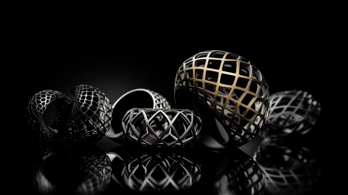
    The jewelry industry has always been at the forefront of innovation, incorporating new materials and techniques to create stunning pieces of wearable art. In recent years, 3D printing technology has become an increasingly important tool in the world of jewelry design and manufacturing. The ability to create intricate, customizable, and cost-effective designs has opened up a realm of possibilities for both established brands and independent designers alike.

    In this blog post, we will delve into the fascinating world of 3D printed jewelry, exploring its rich history, current trends, and the exciting opportunities it presents for the future. By understanding the evolution of 3D printing in the jewelry industry, as well as the hardware and materials used, designers and manufacturers can make informed decisions about how to best integrate this technology into their own businesses. So, let’s begin our journey into the captivating world of 3D printed jewelry and uncover the potential it holds for revolutionizing the industry.

    3D Printing Jewelry Market: A Brief History, Current Trends, and Future Prospects

    The use of 3D printing in jewelry can be traced back to the 1990s when it was initially employed for creating investment casting patterns. This early application allowed for the production of intricate designs that were difficult to achieve using traditional wax carving techniques. As the technology evolved, 3D printing was also used to support vulcanized mold production, enabling the creation of more complex and accurate molds. The advent of directly-printed jewelry further expanded the possibilities for designers, allowing them to bring their intricate visions to life with unparalleled precision.

    Today, 3D printing has found its way into various aspects of the jewelry industry, including the production of rings, earrings, pins, cufflinks, and other small accessories. It has also been utilized in the creation of timepieces, watches, and even “smart” accessories and wearable technologies. The rise of the “metaverse” has seen 3D printed jewelry make its way into the digital realm, while the growing popularity of non-fungible tokens (NFTs) has given rise to virtual jewelry pieces with real-world value. The COVID-19 pandemic has also had an impact on labor availability and material costs, further highlighting the advantages of 3D printing as a more efficient and cost-effective production method.

    The jewelry industry has faced several challenges, including consolidation and the rise of e-commerce, which have forced stakeholders to adapt to a rapidly changing landscape. In response, 3D printing hardware has seen significant advancements, such as reduced costs for polymer printers, improvements in high-speed printing technologies for larger production, and innovations in metal binder jetting for mass production of direct precious metal parts. Additionally, the development of bound metal filament printing has opened up access to low-cost metal 3D printing options.

    3D printing technology has presented several strategic opportunities for the jewelry industry, including the compression of traditionally analog and craft processes. By directly printing investment casting patterns, creating 3D-printed patterns for mold production, or even using 3D-printed pattern molds, manufacturers can streamline their operations and increase efficiency. The development of custom retail platforms and the ability to mass-customize premium jewelry has given businesses a competitive edge in the market. Furthermore, the geometric complexity achievable with 3D printing has led to new stylistic opportunities and design possibilities, allowing artists to push the boundaries of creativity in their work.

    Polymer 3D Printing in Jewelry: Hardware and Materials

    Two main technologies dominate the polymer 3D printing landscape for the jewelry market: vat photopolymerization and material jetting. Vat photopolymerization is a process in which a vat of liquid photopolymer resin is selectively cured using a light source, layer by layer, to create the desired object. This technology includes subcategories such as stereolithography (SLA), digital light processing (DLP), and continuous 3D printing.

    Material jetting, on the other hand, involves depositing droplets of liquid photopolymer onto a build platform and then curing them with ultraviolet (UV) light. The process is similar to inkjet printing and can create highly detailed, smooth, and accurate parts. Material jetting is especially effective for producing castable wax patterns, which are widely used in the jewelry industry.

    Several key players have emerged in the vat photopolymerization space, each offering unique platforms catering to the needs of the jewelry industry. Some of the most notable vendors include Formlabs, with their Form 3 and Form 3L printers, which utilize low-force stereolithography (LFS) technology; EnvisionTEC, which offers a range of DLP-based 3D printers like the Perfactory series; and Carbon, which has developed the innovative Digital Light Synthesis (DLS) technology for continuous 3D printing. These platforms provide jewelers with the ability to create highly detailed and intricate designs, making them ideal for various jewelry applications.

    A wide array of vat photopolymerization materials are available for jewelry applications, each with its own unique properties and advantages. Castable resins are among the most popular materials, as they allow for the creation of highly detailed investment casting patterns that can be burned out cleanly during the casting process. These materials often contain wax or other additives that facilitate a smooth burnout, resulting in high-quality castings.

    In addition to castable resins, there are materials designed specifically for creating mold patterns, such as those used in vulcanized mold production. These materials typically offer high dimensional accuracy, stability, and surface quality, making them ideal for the production of intricate jewelry pieces. Other vat photopolymerization materials include flexible, tough, and high-temperature resins, which can be used for various applications in the jewelry industry, such as design and fit verification models or the creation of unique wearable pieces.

    Metal 3D Printing for Jewelry: Hardware and Materials

    The metal 3D printing landscape for the jewelry market is marked by the presence of several key vendors, each offering innovative technologies and solutions. Some of the major players in this space include EOS, which provides a range of direct metal laser sintering (DMLS) systems; SLM Solutions, a pioneer in selective laser melting technology; Desktop Metal, which has developed the Studio System for bound metal deposition (BMD); and ExOne, a leader in binder jetting technology for metal 3D printing. These vendors have developed systems that cater to the unique needs of the jewelry industry, enabling the creation of intricate and high-quality metal pieces.

    Binder jetting has emerged as a promising technology for precious metal 3D printing in the jewelry market. In this process, a liquid binder is selectively deposited onto a powder bed of metal particles, layer by layer, to create the desired object. Once the printing process is complete, the part is sintered in a furnace to remove the binder and fuse the metal particles together, resulting in a solid, dense piece.

    The advantages of binder jetting for precious metal printing include its ability to produce complex geometries, reduced material waste, and the potential for mass production. Vendors like ExOne and Desktop Metal are pushing the boundaries of binder jetting technology for precious metal printing, offering solutions that can cater to the high-quality requirements of the jewelry industry.

    A variety of precious metals can be used in metal 3D printing for the jewelry market, including gold, silver, and platinum. Each metal offers unique properties and aesthetic qualities, making them suitable for different applications and designs.

    Gold is a popular choice for 3D-printed jewelry due to its versatility, durability, and timeless appeal. It is available in various alloys, such as yellow, white, and rose gold, providing jewelers with a range of options to suit their designs. Silver, while less expensive than gold, is another popular choice for metal 3D printing in the jewelry market. Its affordability, combined with its attractive luster and excellent thermal conductivity, makes silver an ideal material for creating intricate and detailed pieces.

    Platinum, one of the rarest and most valuable metals, is also used in metal 3D printing for the jewelry market. Its high durability, resistance to tarnish, and hypoallergenic properties make it a highly sought-after material for high-end jewelry pieces. As metal 3D printing technologies continue to evolve, the range of materials available for the jewelry market is likely to expand, offering even more possibilities for creating stunning and unique pieces.

    3D Printing Jewelry Market Forecast: 2023-2033

    The 3D printing jewelry market is expected to experience significant growth over the next decade, driven by advancements in hardware, materials, and software technologies. As the adoption of 3D printing in the jewelry industry continues to increase, hardware shipments and revenues are projected to rise steadily. Both polymer and metal 3D printing systems will see a surge in demand, with a particular emphasis on systems tailored to the unique needs of the jewelry market.

    The growth in hardware shipments and revenues can be attributed to various factors, such as the decreasing cost of 3D printers, increased accessibility for small businesses and independent designers, and the development of high-speed polymer and metal printing technologies. These advancements are expected to fuel the expansion of the 3D printing jewelry market and create new opportunities for manufacturers, designers, and consumers alike.

    The materials segment of the 3D printing jewelry market is also projected to grow rapidly, with a focus on both polymer and metal materials. As more vendors enter the market and develop innovative materials for 3D printing, jewelers will have access to a wider variety of options, allowing for increased design freedom and enhanced product offerings.

    The polymer materials market is expected to benefit from the development of new photopolymers and resins specifically designed for the jewelry industry. These materials will offer improved mechanical properties, increased detail resolution, and enhanced surface finish quality, making them ideal for use in 3D-printed jewelry applications.

    The metal materials market will be driven by the development of new alloys and metal powders for binder jetting and other metal 3D printing technologies. These materials will enable jewelers to create intricate, high-quality pieces in precious metals like gold, silver, and platinum, expanding the possibilities for innovative and unique designs.

    As the 3D printing jewelry market continues to evolve, there will be a growing demand for specialized services and software tailored to the industry’s unique requirements. This may include design platforms that facilitate the creation of intricate geometries, optimization tools that ensure efficient material usage and high-quality printing, and software solutions that streamline production workflows. The growth in services and software will further enable jewelers to leverage the benefits of 3D printing, ultimately driving the continued expansion of the market.

    The 3D printing jewelry market is poised for significant growth over the next decade, with advancements in hardware, materials, services, and software all contributing to the industry’s expansion. As 3D printing technologies become more accessible, affordable, and versatile, jewelers of all sizes will be able to harness the benefits of additive manufacturing to create innovative, high-quality pieces that cater to the evolving tastes of consumers.

    The jewelry industry must continue to embrace the possibilities presented by 3D printing and invest in the development and adoption of new technologies. By staying at the forefront of innovation, jewelers can capitalize on the numerous opportunities for growth, increased efficiency, and enhanced design capabilities that 3D printing offers. As the market continues to evolve, those who are willing to adapt and invest in the future of 3D printing will be well-positioned to thrive in the competitive landscape of the jewelry industry.

    As the 3D printing jewelry market continues to grow, so too will the opportunities for collaboration and innovation between designers, manufacturers, and consumers. The future of the jewelry industry is undoubtedly intertwined with the continued development of 3D printing technologies, and those who embrace this evolution will play a crucial role in shaping the future of jewelry design and production. With its vast potential for creativity, efficiency, and customization, 3D printing is set to revolutionize the jewelry industry and redefine what is possible in the world of design and manufacturing.

  • Electron Beam Powder Bed Fusion (PBF-EB/M): Process, Design and Applications

    Electron Beam Powder Bed Fusion (PBF-EB/M): Process, Design and Applications

    Electron beam powder bed fusion is a metal additive manufacturing process in which an electron beam selectively melts regions of a powder bed under vacuum. The current standardized designation is PBF-EB/M: powder bed fusion using an electron beam for metallic materials.

    “Electron Beam Melting” or EBM is a familiar commercial and historical term. PBF-EB/M is the clearer process-category name and distinguishes powder-bed systems from wire-fed electron-beam directed energy deposition.

    How PBF-EB/M works

    1. Build preparation: The released part geometry is oriented, supported, nested and converted into a machine-specific build strategy.
    2. Vacuum generation: The chamber is evacuated so the electron beam can travel with limited scattering and reactive alloys can be processed with reduced atmospheric exposure.
    3. Powder spreading: A controlled powder layer is deposited across the build area.
    4. Preheating: A defocused, rapidly scanned beam heats and partially consolidates the powder bed. This helps control charging, powder movement and thermal gradients.
    5. Selective melting: A focused electron beam melts the cross-section of the part according to the build file.
    6. Layer repetition: The platform is lowered, new powder is spread and the cycle repeats.
    7. Cooling and recovery: After the build, the hot powder cake and components cool before powder recovery and part removal.
    8. Post-processing: Supports, machining stock and surface condition are addressed through the qualified downstream route.

    Why vacuum and preheating matter

    The electron beam is generated and steered electromagnetically. A vacuum environment reduces collisions between electrons and gas molecules and limits oxidation of reactive alloys. Unlike many laser powder-bed systems, PBF-EB/M generally operates with a substantially elevated powder-bed temperature.

    Preheating can reduce residual stress and distortion, but it also changes powder handling. The surrounding powder may become a lightly sintered cake that supports the part and must later be broken down and recovered. The preheat strategy is also critical for avoiding electrostatic powder movement, often described as powder “smoking.”

    PBF-EB/M vs laser powder bed fusion

    CharacteristicPBF-EB/MPBF-LB/M
    Energy sourceElectron beamLaser beam
    AtmosphereVacuum, sometimes with controlled gas addition depending on platformTypically inert gas
    Powder-bed temperatureGenerally high due to preheatingPlatform and alloy dependent; commonly lower than PBF-EB
    Beam steeringElectromagnetic and very fast, without mechanical scanning mirrorsOptical scanner and galvanometer system
    Residual stressOften lower because the build remains hotCan be higher, requiring strong support and stress-control strategies
    Surface and feature resolutionTypically rougher and less suited to the finest featuresOften finer detail and smoother as-built surfaces
    Powder recoveryRemoval from a partially sintered cake can be intensiveLoose-powder recovery is generally more direct
    Material rangeHistorically strongest in selected conductive alloys, especially titaniumBroader commercial alloy and machine ecosystem
    Support functionSupports mainly provide thermal anchoring, stability and location; the powder cake provides mechanical supportSupports commonly provide thermal conduction, anchoring and mechanical stability

    Neither process is universally superior. The choice depends on alloy, geometry, resolution, thermal behavior, production volume, qualification and downstream operations.

    Materials

    PBF-EB/M requires electrically conductive feedstock and a stable relationship between powder, preheat and melt strategy. Commercial maturity has historically been strongest for titanium alloys and cobalt-chromium, with platform-specific routes for nickel alloys and expanding research or industrialization in refractory materials.

    • Ti-6Al-4V and Ti-6Al-4V ELI: aerospace structures and orthopedic implants
    • Cobalt-chromium alloys: medical and dental applications where the qualified route supports them
    • Nickel alloys: selected high-temperature applications, with capability dependent on machine and parameter maturity
    • Pure metals and refractory materials: active development areas including tungsten for energy and defense applications

    A published alloy name does not establish production capability. Feedstock specification, machine platform, parameter set, post-processing and inspection must be qualified as one route.

    Design considerations

    ISO/ASTM 52911-3 provides process-specific design guidance for PBF-EB of metallic materials. Practical design reviews should address:

    • Orientation: balance feature quality, thermal stability, powder removal, supports, machining and inspection.
    • Feature resolution: do not transfer PBF-LB minimum-feature assumptions directly to PBF-EB.
    • Down-facing surfaces: expect roughness, attached particles and geometry-dependent limits.
    • Supports and anchors: design for thermal transfer, positional stability and removal.
    • Powder removal: provide access for breaking and extracting the sintered powder cake from channels and cavities.
    • Machining stock: add material to datums, bores, sealing surfaces and fatigue-critical regions.
    • Nesting: stacked production can improve build utilization but complicates recovery, traceability and thermal interaction.
    • Inspection access: complex internal features must remain inspectable or supported by validated process evidence.

    Microstructure and properties

    The elevated build temperature and directional thermal history can create process-specific texture, grain morphology and phase condition. Properties depend on build orientation, location, section thickness, chemistry, heat treatment, HIP and surface condition.

    Low residual stress does not mean zero distortion or automatic fatigue performance. As-built roughness, near-surface imperfections and internal defects can still control life. Material data should match the exact production route and part condition.

    Typical imperfections and process risks

    RiskPossible contributorsControl approach
    Lack of fusionInsufficient energy, poor overlap, contaminated or uneven powderQualified parameters, powder control, monitoring and volumetric inspection
    Gas or process porosityFeedstock condition, melt instability or entrapped gasFeedstock specification, process stability and validated thermal route
    Powder smokingElectrostatic charging and inadequate preheat/consolidationPlatform-specific preheat strategy and powder qualification
    Surface-connected irregularitiesDownskin, attached particles, supports and powder interactionOrientation, design allowance, machining and surface finishing
    Dimensional errorThermal distortion, beam calibration, compensation and recovery damageMachine control, calibrated compensation and dimensional inspection
    Contamination or chemistry driftPowder reuse, handling, chamber condition and exposureMaterial genealogy, testing, reuse rules and housekeeping

    ISO/ASTM 52948:2026 provides a common classification of imperfections that can occur in both laser- and electron-beam metal powder bed fusion. It does not define universal acceptance limits; those remain application and engineering-authority decisions.

    Post-processing

    • Powder-cake removal and controlled powder recovery
    • Part separation and support removal
    • Heat treatment or HIP where required by the route
    • Machining of datums, interfaces and critical surfaces
    • Surface finishing and cleaning
    • Dimensional, NDT, material and functional verification

    The high build temperature can reduce the need for a separate stress-relief step in some qualified routes, but post-processing requirements must be established from material and application evidence rather than assumed.

    Applications

    Orthopedic implants

    PBF-EB/M has a long industrial history in titanium orthopedic components. The process can produce porous or lattice regions for bone ingrowth alongside dense structural regions, subject to validated cleaning, fatigue, biocompatibility and regulatory controls.

    Aerospace

    The process is attractive for titanium components that benefit from reduced residual stress, stacked production or complex geometry. Aerospace use requires strict machine, material, operator, post-processing and inspection qualification.

    Energy, defense and refractory materials

    Open and industrial PBF-EB platforms are being developed for materials such as tungsten and other difficult-to-process metals. These applications are promising but should be described by demonstrated route maturity rather than broad claims about the process category.

    Economics and production planning

    PBF-EB/M economics are influenced by much more than beam speed:

    • Vacuum and preheat cycle time
    • Build height and nesting density
    • Cooling and powder-cake recovery
    • Powder refresh, testing and reuse
    • Support removal and machining
    • Inspection and accepted-part yield
    • Machine availability, cathode life and maintenance

    Fast electromagnetic beam movement can support high productivity, but cycle economics must include the complete hot-build and recovery route.

    When PBF-EB/M is a strong candidate

    • The alloy and application already have a mature PBF-EB route.
    • Elevated build temperature provides a meaningful residual-stress or cracking advantage.
    • The geometry tolerates the process’s feature-resolution and surface limitations.
    • Stacked production or efficient beam scanning improves accepted-part economics.
    • Vacuum processing benefits a reactive material.
    • Powder recovery, machining and inspection are available.

    PBF-EB/M is not wire-fed EBAM

    PBF-EB/M spreads powder across a bed and selectively melts each layer. Wire-fed electron-beam AM feeds wire directly into a melt pool and belongs to directed energy deposition, usually DED-EB/M. The latter has much higher deposition rates and supports large near-net preforms, but provides lower geometric resolution and requires substantial machining.

    Conclusion

    Electron beam powder bed fusion is a distinct industrial process with a hot powder bed, vacuum environment and fast electromagnetic beam control. Its value is strongest where material, geometry and qualification align with those characteristics. Process selection should compare the complete route—including recovery, machining, inspection and accepted-part yield—rather than relying on generic claims about speed or material utilization.

    Related Addithive resources: Wire-Fed Electron Beam Directed Energy Deposition · Metal AM Process Selection

    References and further reading

  • Nondestructive Testing for Additive Manufacturing: Methods, Defects and Limitations

    Nondestructive Testing for Additive Manufacturing: Methods, Defects and Limitations

    Nondestructive testing (NDT) is essential for additive manufacturing, but no single method can guarantee that a complex AM part is defect-free. Inspection capability depends on the process, alloy, geometry, surface condition, defect type, defect orientation, required resolution and acceptance criteria.

    The correct question is not “Which NDT method is best for AM?” It is “Which combination of methods can detect the credible defects in this specific part with the required probability of detection?”

    Why AM inspection is different

    Metal additive manufacturing can produce internal channels, lattices, thin walls and highly integrated geometries that are difficult to inspect using methods developed for simple wrought or machined parts. AM defects can also be small, irregular, directionally oriented and distributed differently across the build.

    Inspection planning therefore begins with the complete manufacturing route: feedstock, machine, process parameters, build orientation, heat treatment, hot isostatic pressing, machining and surface finishing. Post-processing can close, reveal, reshape or remove indications, so the inspection stage matters.

    Common defect and imperfection classes

    ImperfectionTypical causeInspection challenge
    Lack of fusionInsufficient energy, poor overlap, contamination or unstable powder layerOften planar and orientation-sensitive
    Gas porosityEntrapped gas, powder condition or melt-pool behaviorSmall rounded pores may require high volumetric resolution
    Keyhole porosityExcessive energy density and unstable deep melt poolMay appear as irregular or elongated pores
    CracksResidual stress, hot cracking, thermal cycling or alloy sensitivityThin planar cracks can be difficult to detect when poorly oriented to the inspection beam
    Inclusions or contaminationForeign material, oxide, spatter or handling contaminationDetectability depends on density contrast and size
    Dimensional deviationShrinkage, distortion, support failure, thermal behavior or post-processingInternal geometry may be inaccessible to conventional metrology
    Surface-connected discontinuitiesSupport removal, machining damage, cracking or incomplete fusionRough as-built surfaces can create false or masked indications
    Trapped powderInsufficient escape paths or ineffective cleaningMay be hidden inside channels and cavities

    X-ray computed tomography

    Industrial X-ray computed tomography (CT) is one of the most powerful tools for AM because it can reconstruct internal and external geometry in three dimensions. It can detect porosity, lack-of-fusion regions, inclusions, dimensional deviations, trapped powder and inaccessible internal features.

    CT is not unlimited. Detectability depends on voxel size, focal spot, detector, material density, wall thickness, part diameter, scan geometry, reconstruction and analysis settings. A large dense nickel-alloy part cannot be inspected at the same resolution as a small aluminum coupon. CT resolution claims must be connected to the actual part and minimum defect size.

    • Strengths: volumetric data, internal geometry, pore distribution and dimensional comparison.
    • Limitations: cost, scan time, penetration, artifacts, resolution versus part size and interpretation complexity.
    • Best practice: validate the technique using representative artifacts or seeded flaws and document the scan and analysis parameters.

    Conventional radiography

    Two-dimensional radiography can detect volumetric discontinuities and density variations, but it compresses three-dimensional information into a projection. Overlapping features and complex geometry can mask defects. Planar flaws aligned unfavorably to the beam may be difficult to see.

    Radiographic inspection setup
    Radiographic testing

    Ultrasonic testing

    Ultrasonic testing can detect internal cracks, lack of fusion and other discontinuities in suitable geometries. Phased-array and advanced full-matrix techniques can improve coverage and imaging. However, rough surfaces, thin sections, complex curvature, internal channels and anisotropic microstructures can complicate coupling, wave propagation and signal interpretation.

    Machined inspection surfaces or purpose-designed access may be needed. Calibration blocks and reference reflectors should represent the alloy, heat treatment, geometry and expected defect orientation as closely as practical.

    Ultrasonic inspection of an aerospace component

    Liquid penetrant testing

    Liquid penetrant testing is effective for surface-breaking discontinuities on nonporous, clean surfaces. As-built AM roughness can retain penetrant and generate excessive background. The method is often more reliable after machining or surface finishing, when the inspection surface and cleaning process are controlled.

    Penetrant testing cannot detect sealed internal defects and should not be treated as evidence of volumetric integrity.

    Liquid penetrant inspection

    Magnetic particle testing

    Magnetic particle testing can reveal surface and near-surface discontinuities in ferromagnetic alloys. It is not applicable to titanium, aluminum, austenitic stainless steels or most nickel alloys. Surface roughness, geometry and residual magnetism must be controlled.

    Magnetic particle inspection

    Eddy current testing

    Eddy current methods detect surface and near-surface discontinuities in electrically conductive materials. They can be sensitive to small cracks, but probe access, lift-off, curvature, roughness, conductivity variation and geometry affect performance. Eddy current inspection is generally local rather than a complete volumetric method.

    Eddy current induction principle

    Optical and dimensional inspection

    Coordinate measuring machines, structured-light scanners, laser scanners and optical microscopy verify dimensional and surface requirements. They do not replace volumetric NDT. Line-of-sight systems cannot measure hidden channels, and highly reflective or rough surfaces may require preparation or specialized scanning strategies.

    In-situ monitoring is not final NDT

    Melt-pool sensors, layer imaging, recoater monitoring, acoustic signals and machine logs can identify process anomalies. These data improve traceability and may support adaptive control. However, an anomaly signal is not automatically a verified defect, and the absence of an alarm does not prove that the part is acceptable.

    In-situ monitoring must be correlated with destructive testing, NDT and production outcomes before it can support acceptance decisions. It is best viewed as one layer in a broader process-control and inspection strategy.

    Probability of detection and validation

    A method may detect a large laboratory defect without reliably detecting the smallest critical defect in production. For safety-critical applications, inspection capability should be demonstrated using representative part thickness, geometry, alloy, surface condition and defect type.

    • Define the minimum relevant defect size and orientation.
    • Use representative reference standards, test artifacts or intentionally seeded flaws.
    • Control equipment, calibration, software, analysis thresholds and operator qualification.
    • Document false-call risk and inspection blind zones.
    • Revalidate the method when geometry, material, surface or equipment changes materially.

    How to build an AM inspection plan

    1. Identify critical functions and credible failure modes.
    2. Map likely imperfection types to the AM process and post-processing route.
    3. Define inspection zones and required detection capability.
    4. Select complementary surface, dimensional and volumetric methods.
    5. Design inspection access into the part where possible.
    6. Validate methods on representative artifacts or seeded flaws.
    7. Set acceptance criteria based on engineering significance, not merely visibility.
    8. Link results to build records, material genealogy and configuration control.

    Quick method comparison

    MethodBest atMain limitation in AM
    X-ray CTInternal geometry and volumetric defectsResolution, penetration, artifacts, cost and part-size trade-off
    RadiographyVolumetric density changes in suitable geometriesFeature overlap and limited 3D localization
    Ultrasonic testingInternal cracks and planar defects with suitable accessRough surfaces, complex geometry and anisotropic propagation
    Liquid penetrantSurface-breaking defectsAs-built roughness and no subsurface capability
    Magnetic particleSurface/near-surface defects in ferromagnetic materialsMaterial limitation and surface sensitivity
    Eddy currentSmall surface/near-surface cracks in conductive materialsLocal access, lift-off and geometry sensitivity
    Optical/CMMExternal dimensions and visible surface conditionNo internal volumetric capability
    In-situ monitoringProcess anomalies and traceabilityRequires correlation; not direct proof of final part integrity

    Conclusion

    Reliable AM inspection combines process knowledge, complementary NDT methods and validated detection capability. Complex geometry does not make a part uninspectable by definition, but it can create blind zones that must be understood during design. The inspection plan should be developed with the part and manufacturing route, not added after printing.

    Related Addithive research: Aerospace AM Qualification Guide · Design for LPBF

    References and further reading

  • Additive Manufacturing: Redefining Mobility Production at Point of Use

    Additive Manufacturing: Redefining Mobility Production at Point of Use

    Additive Manufacturing, or 3D-printing, technology has been a significant advancement in the manufacturing industry, with one of its most frequently mentioned benefits being the ability to produce parts at the point of use. This technology allows for the downloading of a digital file and the creation of the part on-site, which has the potential to greatly compress supply chains, lead times, inventories, and design iterations for custom parts.

    The mobility industry, including automobile, aerospace, and transportation sectors, is one that demands precision, high-quality, and cost-effective solutions. Additive Manufacturing technology, with its ability to create complex geometries, lightweight designs, and rapid prototyping, is uniquely suited to meet the demands of the mobility industry. However, the viability of this technology for production at the point of use is not universal and depends on several factors, such as size, materials, build time, manufacturing complexity, cost, and competing technologies.

    For the mobility industry, one of the key challenges is the size of the parts that can be produced using Additive Manufacturing technology. This is due to the limited build volume of the printer, which can increase the build time and cost for larger parts. Additionally, the quality of the part may be compromised due to the limitations of the printing process, which may not be suitable for high-stress applications, such as those found in the mobility industry.

    Another challenge for the mobility industry is the limited range of materials that can be used for Additive Manufacturing. Although the range of materials that can be used has expanded with advancements in materials science, the majority of Additive Manufacturing materials are limited to plastics and some metals. This may not be suitable for applications that require high-strength materials, such as those found in the aerospace or automotive industries.

    Despite these challenges, the mobility industry is investing in Additive Manufacturing capacity for production at the point of use. One of the key benefits of this technology is the ability to reduce supply chain and inventory costs by producing parts on-site. Additionally, the ability to create complex geometries and lightweight designs can lead to a reduction in fuel consumption and emissions, which is crucial in the transportation industry.

    Moreover, Additive Manufacturing technology can significantly reduce the design iterations required for custom parts, leading to a faster time-to-market for new products and an increase in the speed of innovation. For instance, automotive companies can use Additive Manufacturing technology to rapidly prototype and test new designs, which can reduce the time and cost associated with traditional manufacturing methods.

    However, it is essential for companies in the mobility industry to evaluate the feasibility and benefits of Additive Manufacturing technology on a case-by-case basis. This requires a deep understanding of the technology and its capabilities, as well as an evaluation of the costs and benefits associated with using Additive Manufacturing technology for production at the point of use.

    In conclusion, Additive Manufacturing technology is a significant advancement for the mobility industry, providing unique advantages such as the ability to produce parts at the point of use and reduce supply chain and inventory costs. However, the viability of this technology for production at the point of use is dependent on several factors, including the size and complexity of the part, the materials used, and the cost of the technology. Therefore, it is important for the mobility industry to carefully evaluate the feasibility and benefits of Additive Manufacturing technology for their specific needs.

  • Aerospace Additive Manufacturing: Applications, Qualification and Production Economics

    Aerospace Additive Manufacturing: Applications, Qualification and Production Economics

    Additive manufacturing has become an established aerospace production tool for selected components, but it is not a universal replacement for casting, forging, machining or composites. Its strongest cases combine a difficult geometry, expensive material, low-to-medium volume and a qualification path that can control the complete manufacturing route.

    In aerospace, the value of AM is not the printed shape alone. The product is the qualified system of design, feedstock, machine, parameters, post-processing, inspection and production control.

    Where additive manufacturing creates aerospace value

    Value mechanismTypical aerospace opportunityMain constraint
    Part consolidationCombine manifolds, ducts, brackets or fluid hardware into fewer componentsInspection, repairability and configuration control
    Thermal-fluid performanceConformal cooling, compact heat exchangers and optimized flow passagesInternal-surface quality, cleaning and pressure testing
    LightweightingTopology-optimized structures and lattice-supported designsFatigue, damage tolerance and load-path verification
    Buy-to-fly reductionNear-net titanium or nickel-alloy preformsMachining, distortion and accepted-part yield
    Lead-time reductionLong-lead spares, tooling and low-volume replacement partsDigital-data authority and recurring qualification cost
    Repair or feature additionRestore worn surfaces or add local material with DEDSubstrate condition, interface integrity and inspection
    Rapid developmentPrototype combustion, propulsion and test hardwarePreventing prototype evidence from being mistaken for production maturity

    Aerospace application map

    Propulsion and hot-section hardware

    AM is attractive for fuel nozzles, injectors, combustor features, heat exchangers, turbomachinery components and rocket propulsion hardware because these parts often benefit from internal passages, thin walls and consolidated assemblies. Metal powder bed fusion is common for complex precision geometry; directed energy deposition can serve larger near-net shapes and repair.

    The difficulty is not merely achieving density. Qualification must address microstructure, anisotropy, surface-connected defects, internal passages, residual stress, heat treatment, HIP, machining and fatigue-critical surfaces.

    Heat exchangers and thermal management

    Compact heat exchangers are among the clearest geometry-driven AM applications. Thin walls, cellular cores and complex channels can increase heat-transfer area while reducing part count. The design must still account for minimum wall capability, pressure containment, channel cleaning, dimensional inspection and leak testing.

    Structural brackets and airframe components

    Topology optimization can reduce mass in brackets, mounts and structural fittings. The business case is strongest where weight produces meaningful life-cycle value and production volume does not justify dedicated tooling. Structural use requires a credible load path, representative material data, damage-tolerance assumptions and controlled surface condition.

    Space systems

    Launch vehicles and spacecraft often combine low production volume with high geometric complexity and strong pressure to reduce mass and development time. Applications include propulsion hardware, tanks, antennas, thermal components and structural parts. Faster iteration is valuable, but flight acceptance still depends on requirements, test evidence and repeatable manufacturing.

    Tooling, fixtures and factory support

    Polymer and metal AM can produce drill guides, inspection fixtures, lay-up tools, protective covers, assembly aids and ergonomic devices. These applications often require less qualification than flight hardware and can deliver faster operational value. Tooling should still be reviewed for dimensional stability, temperature, chemical exposure and safe load capacity.

    Repair and sustainment

    Directed energy deposition and cold-spray routes can restore material or add features to high-value hardware. The process is most credible when damage removal, substrate preparation, interface metallurgy, heat treatment and inspection are treated as one approved repair specification.

    Process selection for aerospace

    Process familyStrong aerospace useMain limitations
    Laser powder bed fusionComplex metal parts, propulsion, heat exchangers and bracketsBuild size, support removal, residual stress and surface condition
    Electron-beam powder bed fusionSelected titanium components and hot-build applicationsFeature resolution, powder-cake recovery and narrower commercial material ecosystem
    Wire or powder DEDLarge near-net shapes, repair and feature additionCoarse geometry, thermal distortion, machining and inspection
    Binder jettingPotential serial production of smaller metal parts and casting toolingGreen-part handling, sintering shrinkage and furnace control
    Polymer powder bed fusionDucts, interiors, tooling and noncritical production partsFlammability, aging, moisture and material-property control
    Vat photopolymerizationPatterns, tooling, models and selected cabin or ground applicationsResin aging, post-cure, UV and temperature limits
    Material extrusionFixtures, tooling, patterns and large-format factory aidsAnisotropy, dimensional stability and surface quality

    Process selection should be based on the finished component route rather than the printer alone. See Addithive’s metal AM process-selection guide.

    The aerospace qualification chain

    1. Requirements and criticality: Define function, environment, life, failure consequences and regulatory basis.
    2. Design allowables: Establish material data for the exact machine, parameter, orientation, heat treatment and surface condition.
    3. Feedstock control: Specify chemistry, morphology, contamination, storage, reuse and genealogy.
    4. Machine qualification: Control installation, calibration, maintenance, software, firmware and parameter release.
    5. Process characterization: Understand build location, geometry, thermal history and defect sensitivity.
    6. Post-processing qualification: Validate heat treatment, HIP, support removal, machining, finishing and cleaning.
    7. Inspection strategy: Combine dimensional inspection, material testing, surface methods and volumetric NDT.
    8. Part substantiation: Demonstrate static, fatigue, pressure, thermal and environmental performance as applicable.
    9. Production surveillance: Monitor machines, coupons, feedstock, nonconformances and process drift.
    10. Change control: Define the evidence required for changes to machine, site, software, parameters, material or suppliers.

    The FAA’s active Advisory Circular AC 33.15-3 provides an acceptable means for demonstrating compliance for powder-bed-fusion materials used in aircraft engine parts. It also addresses closely related design and manufacturing considerations.

    Defects, surfaces and inspection

    Aerospace AM risk is strongly geometry dependent. Common concerns include lack of fusion, porosity, cracking, surface-connected irregularities, dimensional distortion, trapped powder and machining damage. Internal channels and lattice structures can be difficult to clean and inspect.

    • Use process monitoring to understand events, not as an automatic substitute for acceptance inspection.
    • Machine fatigue-critical and sealing surfaces where required.
    • Choose NDT according to defect orientation, material, thickness and access.
    • Validate powder removal from channels and cavities.
    • Link every inspection result to part, build, location, machine and material lot.

    Related guides: NDT for additive manufacturing and surface finishing for metal AM.

    Aerospace AM economics

    A credible cost comparison includes the complete product life cycle:

    • Design, simulation and qualification
    • Feedstock, supports and build failures
    • Machine, gas, energy and labor
    • Heat treatment, HIP and furnace capacity
    • Support removal, machining and finishing
    • NDT, testing and documentation
    • Rejected parts and change-control cost
    • Assembly reduction, inventory and lead time
    • Fuel, payload, thermal or reliability value during service

    The strongest business cases often have at least two value sources—for example, reduced assembly plus improved thermal performance, or lower buy-to-fly ratio plus shorter raw-material lead time.

    Production-readiness checklist

    1. The AM geometry creates measurable system or supply-chain value.
    2. The selected material and process have a credible qualification route.
    3. Internal features can be cleaned and inspected.
    4. Machining datums and allowances are designed in.
    5. Material data represent the final surface and post-process condition.
    6. Machine, software and parameter changes are controlled.
    7. Production yield and accepted-part cost meet the business case.
    8. Second-source, repair and obsolescence plans are defined.
    9. Digital records support the required product life.
    10. The certification authority and customer agree on the evidence plan.

    Conclusion

    Aerospace additive manufacturing is most valuable when it solves a specific geometry, material or supply-chain constraint. The printer is only one element. Sustainable production requires an integrated design, material, process, post-processing, inspection and certification system with economics measured at the accepted flight-ready part.

    Related Addithive resources: Aerospace AM Qualification Guide · GE Aerospace AM Profile · Airbus AM Profile

    References and further reading

  • Customization, Efficiency and Sustainability in AM — Updated Guide

    Customization, Efficiency and Sustainability in AM — Updated Guide

    This article has been consolidated into the updated AM guide

    The original article presented customization, efficiency and sustainability as broad advantages of additive manufacturing. These topics now appear in Addithive’s updated pillar guide with more precise engineering context and fewer absolute claims.

    What changed

    • Customization is evaluated against design, validation and quality-control cost.
    • Efficiency is compared with tooling, production volume and total post-processing time.
    • Material savings include supports, failed builds, powder refresh and machining stock.
    • Sustainability is assessed at lifecycle and system level rather than assumed from the printing step alone.
    • On-demand production and digital inventory are discussed together with qualification and data-retention constraints.

    The original URL remains live to protect bookmarks and external links, while the updated pillar article is now the authoritative source.