This page was originally published as a forward-looking list of additive manufacturing trends for 2023. It is now preserved as a historical snapshot rather than a current industry outlook.
The original themes—powder bed fusion, automation, new materials, vat photopolymerization, directed energy deposition, binder jetting and production scaling—remain relevant process categories. However, the article used overly promotional language and did not distinguish between technical possibility, commercial adoption and qualified production.
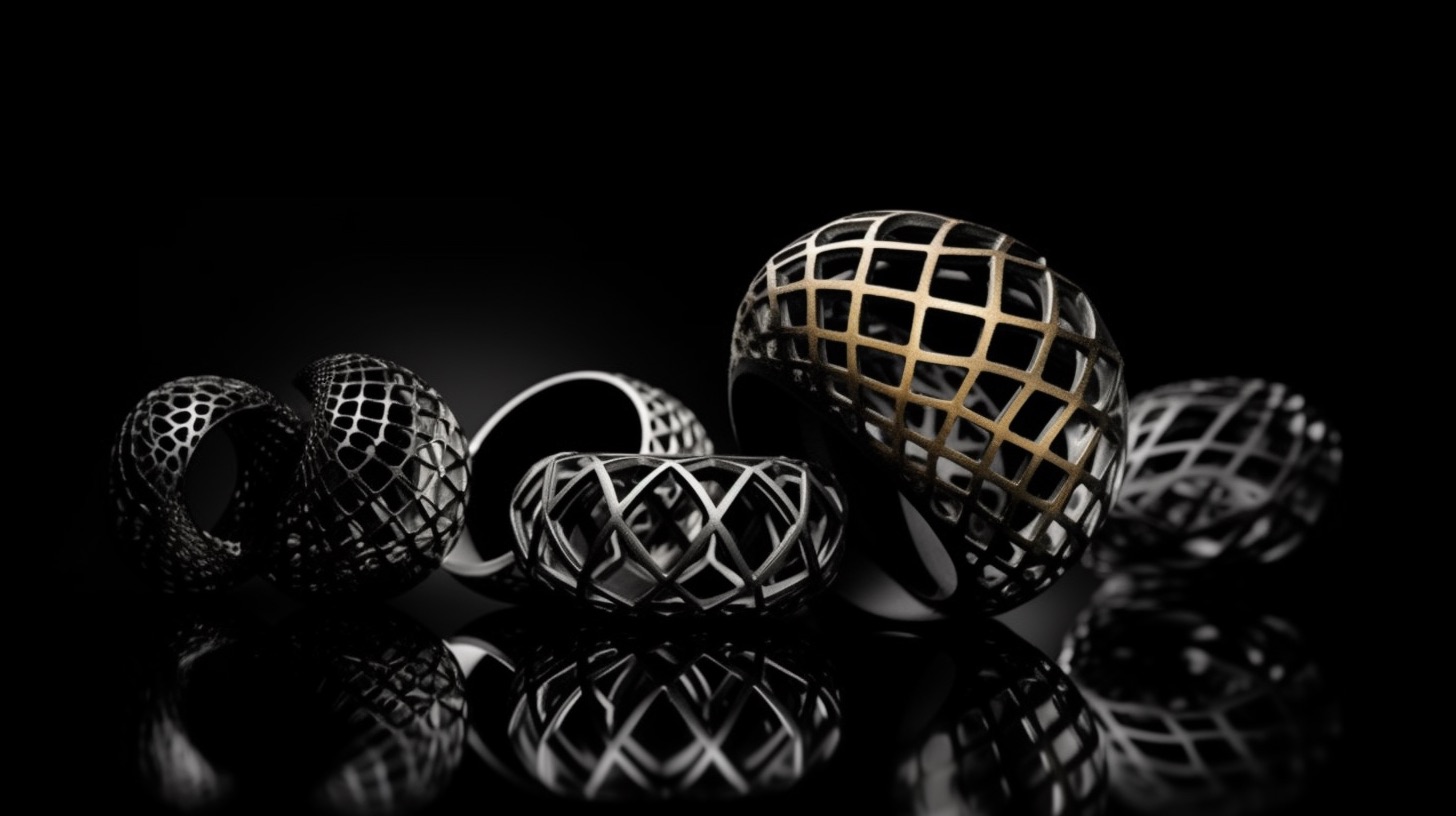
The jewelry industry has always been at the forefront of innovation, incorporating new materials and techniques to create stunning pieces of wearable art. In recent years, 3D printing technology has become an increasingly important tool in the world of jewelry design and manufacturing. The ability to create intricate, customizable, and cost-effective designs has opened up a realm of possibilities for both established brands and independent designers alike.
In this blog post, we will delve into the fascinating world of 3D printed jewelry, exploring its rich history, current trends, and the exciting opportunities it presents for the future. By understanding the evolution of 3D printing in the jewelry industry, as well as the hardware and materials used, designers and manufacturers can make informed decisions about how to best integrate this technology into their own businesses. So, let’s begin our journey into the captivating world of 3D printed jewelry and uncover the potential it holds for revolutionizing the industry.
3D Printing Jewelry Market: A Brief History, Current Trends, and Future Prospects
The use of 3D printing in jewelry can be traced back to the 1990s when it was initially employed for creating investment casting patterns. This early application allowed for the production of intricate designs that were difficult to achieve using traditional wax carving techniques. As the technology evolved, 3D printing was also used to support vulcanized mold production, enabling the creation of more complex and accurate molds. The advent of directly-printed jewelry further expanded the possibilities for designers, allowing them to bring their intricate visions to life with unparalleled precision.
Today, 3D printing has found its way into various aspects of the jewelry industry, including the production of rings, earrings, pins, cufflinks, and other small accessories. It has also been utilized in the creation of timepieces, watches, and even “smart” accessories and wearable technologies. The rise of the “metaverse” has seen 3D printed jewelry make its way into the digital realm, while the growing popularity of non-fungible tokens (NFTs) has given rise to virtual jewelry pieces with real-world value. The COVID-19 pandemic has also had an impact on labor availability and material costs, further highlighting the advantages of 3D printing as a more efficient and cost-effective production method.
The jewelry industry has faced several challenges, including consolidation and the rise of e-commerce, which have forced stakeholders to adapt to a rapidly changing landscape. In response, 3D printing hardware has seen significant advancements, such as reduced costs for polymer printers, improvements in high-speed printing technologies for larger production, and innovations in metal binder jetting for mass production of direct precious metal parts. Additionally, the development of bound metal filament printing has opened up access to low-cost metal 3D printing options.
3D printing technology has presented several strategic opportunities for the jewelry industry, including the compression of traditionally analog and craft processes. By directly printing investment casting patterns, creating 3D-printed patterns for mold production, or even using 3D-printed pattern molds, manufacturers can streamline their operations and increase efficiency. The development of custom retail platforms and the ability to mass-customize premium jewelry has given businesses a competitive edge in the market. Furthermore, the geometric complexity achievable with 3D printing has led to new stylistic opportunities and design possibilities, allowing artists to push the boundaries of creativity in their work.
Polymer 3D Printing in Jewelry: Hardware and Materials
Two main technologies dominate the polymer 3D printing landscape for the jewelry market: vat photopolymerization and material jetting. Vat photopolymerization is a process in which a vat of liquid photopolymer resin is selectively cured using a light source, layer by layer, to create the desired object. This technology includes subcategories such as stereolithography (SLA), digital light processing (DLP), and continuous 3D printing.
Material jetting, on the other hand, involves depositing droplets of liquid photopolymer onto a build platform and then curing them with ultraviolet (UV) light. The process is similar to inkjet printing and can create highly detailed, smooth, and accurate parts. Material jetting is especially effective for producing castable wax patterns, which are widely used in the jewelry industry.
Several key players have emerged in the vat photopolymerization space, each offering unique platforms catering to the needs of the jewelry industry. Some of the most notable vendors include Formlabs, with their Form 3 and Form 3L printers, which utilize low-force stereolithography (LFS) technology; EnvisionTEC, which offers a range of DLP-based 3D printers like the Perfactory series; and Carbon, which has developed the innovative Digital Light Synthesis (DLS) technology for continuous 3D printing. These platforms provide jewelers with the ability to create highly detailed and intricate designs, making them ideal for various jewelry applications.
A wide array of vat photopolymerization materials are available for jewelry applications, each with its own unique properties and advantages. Castable resins are among the most popular materials, as they allow for the creation of highly detailed investment casting patterns that can be burned out cleanly during the casting process. These materials often contain wax or other additives that facilitate a smooth burnout, resulting in high-quality castings.
In addition to castable resins, there are materials designed specifically for creating mold patterns, such as those used in vulcanized mold production. These materials typically offer high dimensional accuracy, stability, and surface quality, making them ideal for the production of intricate jewelry pieces. Other vat photopolymerization materials include flexible, tough, and high-temperature resins, which can be used for various applications in the jewelry industry, such as design and fit verification models or the creation of unique wearable pieces.
Metal 3D Printing for Jewelry: Hardware and Materials
The metal 3D printing landscape for the jewelry market is marked by the presence of several key vendors, each offering innovative technologies and solutions. Some of the major players in this space include EOS, which provides a range of direct metal laser sintering (DMLS) systems; SLM Solutions, a pioneer in selective laser melting technology; Desktop Metal, which has developed the Studio System for bound metal deposition (BMD); and ExOne, a leader in binder jetting technology for metal 3D printing. These vendors have developed systems that cater to the unique needs of the jewelry industry, enabling the creation of intricate and high-quality metal pieces.
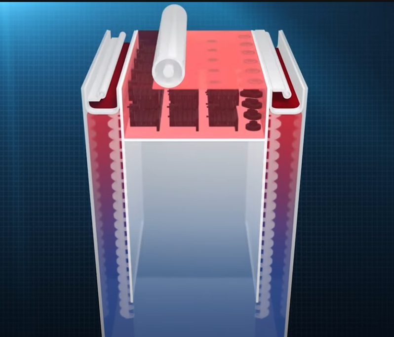
Binder jetting has emerged as a promising technology for precious metal 3D printing in the jewelry market. In this process, a liquid binder is selectively deposited onto a powder bed of metal particles, layer by layer, to create the desired object. Once the printing process is complete, the part is sintered in a furnace to remove the binder and fuse the metal particles together, resulting in a solid, dense piece.
The advantages of binder jetting for precious metal printing include its ability to produce complex geometries, reduced material waste, and the potential for mass production. Vendors like ExOne and Desktop Metal are pushing the boundaries of binder jetting technology for precious metal printing, offering solutions that can cater to the high-quality requirements of the jewelry industry.
A variety of precious metals can be used in metal 3D printing for the jewelry market, including gold, silver, and platinum. Each metal offers unique properties and aesthetic qualities, making them suitable for different applications and designs.
Gold is a popular choice for 3D-printed jewelry due to its versatility, durability, and timeless appeal. It is available in various alloys, such as yellow, white, and rose gold, providing jewelers with a range of options to suit their designs. Silver, while less expensive than gold, is another popular choice for metal 3D printing in the jewelry market. Its affordability, combined with its attractive luster and excellent thermal conductivity, makes silver an ideal material for creating intricate and detailed pieces.
Platinum, one of the rarest and most valuable metals, is also used in metal 3D printing for the jewelry market. Its high durability, resistance to tarnish, and hypoallergenic properties make it a highly sought-after material for high-end jewelry pieces. As metal 3D printing technologies continue to evolve, the range of materials available for the jewelry market is likely to expand, offering even more possibilities for creating stunning and unique pieces.
3D Printing Jewelry Market Forecast: 2023-2033
The 3D printing jewelry market is expected to experience significant growth over the next decade, driven by advancements in hardware, materials, and software technologies. As the adoption of 3D printing in the jewelry industry continues to increase, hardware shipments and revenues are projected to rise steadily. Both polymer and metal 3D printing systems will see a surge in demand, with a particular emphasis on systems tailored to the unique needs of the jewelry market.
The growth in hardware shipments and revenues can be attributed to various factors, such as the decreasing cost of 3D printers, increased accessibility for small businesses and independent designers, and the development of high-speed polymer and metal printing technologies. These advancements are expected to fuel the expansion of the 3D printing jewelry market and create new opportunities for manufacturers, designers, and consumers alike.
The materials segment of the 3D printing jewelry market is also projected to grow rapidly, with a focus on both polymer and metal materials. As more vendors enter the market and develop innovative materials for 3D printing, jewelers will have access to a wider variety of options, allowing for increased design freedom and enhanced product offerings.
The polymer materials market is expected to benefit from the development of new photopolymers and resins specifically designed for the jewelry industry. These materials will offer improved mechanical properties, increased detail resolution, and enhanced surface finish quality, making them ideal for use in 3D-printed jewelry applications.
The metal materials market will be driven by the development of new alloys and metal powders for binder jetting and other metal 3D printing technologies. These materials will enable jewelers to create intricate, high-quality pieces in precious metals like gold, silver, and platinum, expanding the possibilities for innovative and unique designs.
As the 3D printing jewelry market continues to evolve, there will be a growing demand for specialized services and software tailored to the industry’s unique requirements. This may include design platforms that facilitate the creation of intricate geometries, optimization tools that ensure efficient material usage and high-quality printing, and software solutions that streamline production workflows. The growth in services and software will further enable jewelers to leverage the benefits of 3D printing, ultimately driving the continued expansion of the market.
The 3D printing jewelry market is poised for significant growth over the next decade, with advancements in hardware, materials, services, and software all contributing to the industry’s expansion. As 3D printing technologies become more accessible, affordable, and versatile, jewelers of all sizes will be able to harness the benefits of additive manufacturing to create innovative, high-quality pieces that cater to the evolving tastes of consumers.
The jewelry industry must continue to embrace the possibilities presented by 3D printing and invest in the development and adoption of new technologies. By staying at the forefront of innovation, jewelers can capitalize on the numerous opportunities for growth, increased efficiency, and enhanced design capabilities that 3D printing offers. As the market continues to evolve, those who are willing to adapt and invest in the future of 3D printing will be well-positioned to thrive in the competitive landscape of the jewelry industry.
As the 3D printing jewelry market continues to grow, so too will the opportunities for collaboration and innovation between designers, manufacturers, and consumers. The future of the jewelry industry is undoubtedly intertwined with the continued development of 3D printing technologies, and those who embrace this evolution will play a crucial role in shaping the future of jewelry design and production. With its vast potential for creativity, efficiency, and customization, 3D printing is set to revolutionize the jewelry industry and redefine what is possible in the world of design and manufacturing.
Scaling additive manufacturing is not the same as buying a faster printer or adding more machines. Production scale is achieved when the complete system—orders, build preparation, printing, material handling, furnaces, machining, inspection and release—delivers accepted parts at the required rate, cost and quality.
The factory bottleneck is rarely fixed. As print capacity rises, the constraint often moves to depowdering, debinding, sintering, heat treatment, support removal, machining or inspection.
What high-volume AM really means
“High volume” is application dependent. Thousands of personalized dental parts, hundreds of aerospace components and millions of small polymer parts represent very different production systems. A useful definition is the repeatable delivery of demand at target takt time with stable first-pass yield and controlled cost per accepted part.
Metric
Why it matters
Customer takt time
Required interval between accepted finished parts
Accepted parts per build
Real output after scrap and disposition
End-to-end cycle time
Time from released order to part release
First-pass yield
Stability of the full process route
Overall equipment effectiveness
Availability, performance and quality of constrained assets
Cost per accepted part
True economic outcome
Queue time by operation
Location of hidden factory bottlenecks
Engineering touch time
Ability to scale without proportional headcount
The production-rate equation
Printer speed is only one input. Approximate system output can be understood as:
A machine with a short build time can still produce low output if setup is slow, nesting is poor, cooling is long, furnaces are full or inspection rejects parts. Conversely, a slower process can be economical when builds contain many parts and downstream operations are highly automated.
Start with demand segmentation
Do not mix every application into one production model. Segment demand by:
Process and machine family
Material and contamination controls
Part criticality and inspection route
Heat treatment, debinding or sintering recipe
Machining and finishing requirements
Order pattern: repeat, customized or engineering development
Required delivery lead time
Stable repeat products should not compete for the same scheduling rules as development builds and one-off experiments.
Capacity must be modeled across the complete route
Operation
Capacity driver
Common hidden loss
Engineering review
Applications per engineer
Repeated manual quoting and manufacturability review
Build preparation
Jobs released per planner
Manual supports, file repair and approval loops
Printing
Build time and machine availability
Setup, calibration, alarms, cooling and failed builds
Powder/resin recovery
Stations and labor
Manual handling, cleaning and material segregation
Debinding/sintering
Furnace volume and cycle length
Setter limits, shrinkage variation and batch incompatibility
Heat treatment/HIP
Qualified furnace capacity
Long queues and minimum economic batch size
Support removal
Labor, automation and geometry
Damage, variable cycle time and ergonomic constraints
Machining
Fixture and spindle capacity
Difficult datum transfer and interrupted surfaces
Inspection
Technique time and equipment access
CT queues, manual report review and false calls
Quality release
Data completeness and review time
Disconnected records and unresolved deviations
Process-specific scaling models
Polymer powder bed fusion
Technologies such as polymer laser sintering and Multi Jet Fusion can pack many parts into a build without attached supports. Scale depends on nesting density, powder refresh, cooling, breakout, blasting, dyeing and dimensional consistency. A printer farm without automated powder and finishing flow can create large manual queues.
Vat photopolymerization
Projection and masked-light systems can expose a complete layer at once, but total throughput depends on part height, peel or separation mechanics, washing, drying, support removal and post-curing. Resin qualification and cleaning capacity become important at scale.
Metal powder bed fusion
Multi-laser platforms can increase exposure capacity, but the factory must also scale powder handling, build-plate logistics, stress relief, wire EDM, support removal, machining and NDT. More lasers do not automatically produce proportionally more accepted parts.
Metal binder jetting
Printing can be rapid and support-free, but green-part handling, depowdering, debinding, setter design and sintering control define production economics. Furnace capacity and shrinkage variation are often the dominant constraints.
Directed energy deposition
DED can deposit material rapidly, especially for large wire-fed systems. Scale depends on path development, thermal control, machine occupancy, heat treatment, machining and inspection. Gross deposition rate is not final-part takt time.
Nesting and product mix
AM machines often process multiple parts in one batch. This creates opportunities and risks:
Higher nesting density can reduce unit machine cost.
Mixing part types can complicate traceability, heat treatment and release.
A single failed feature or alarm can place an entire build at risk.
Tall parts can determine build time even when the rest of the volume is underused.
Different due dates can create scheduling conflict inside the same build.
Shared builds require clear location, serial-number and material-coupon mapping.
Nesting optimization should balance cost, delivery risk, thermal interaction and quality—not only fill percentage.
Automation priorities
Automation creates the most value when applied to stable, repetitive work. High-impact opportunities include:
Automated order intake and manufacturability screening
Template-based orientation, supports and build release
Material identification and genealogy
Automated powder or resin handling
Robotic part recovery and support removal
Standard fixtures and probing for machining
Automated metrology and report generation
MES routing, electronic travelers and release checks
Analytics for yield, queues and preventive maintenance
Automating an unstable process makes variation faster. Standardize and measure before automating.
First-pass yield is the scaling multiplier
A small yield loss compounds across multiple operations. For example, a build route with 95% yield at printing, 95% at post-processing and 95% at final inspection produces only about 86% overall yield before other losses.
Yield improvement can therefore create more effective capacity than adding another printer. Track defects by operation and distinguish:
Build failure
Dimensional nonconformance
Material-property failure
Post-processing damage
Machining scrap
NDT rejection
Documentation or traceability failure
Factory layout and material flow
Production layout should minimize uncontrolled movement of feedstock, parts and data. Consider:
Separation of incompatible or reactive materials
One-way flow for powder, green parts and finished hardware
Safe transfer to furnaces and depowdering stations
Space for quarantine and nonconforming material
Environmental controls and housekeeping
Ergonomics for repetitive recovery and finishing work
Digital work instructions at the point of use
Expansion space around the real bottleneck, not only printers
Qualification at scale
Scaling introduces new equivalency questions:
Can production move between machines of the same model?
How are multiple lasers, nozzles or print heads compared?
Can a build be transferred to another site or supplier?
What software, firmware or parameter changes require revalidation?
How is furnace and post-process equivalency established?
Which monitoring or inspection data supports reduced testing?
The organization should define equivalency and change-control rules before capacity expansion, not after the original machine becomes overloaded.
Economics of capacity expansion
Before purchasing another machine, compare four options:
Improve yield: remove recurring scrap and rework.
Reduce setup and queue time: standardize builds and balance downstream flow.
Increase nesting or batch efficiency: improve usable output per cycle.
Add or outsource capacity: expand only when the constrained step remains capacity-limited after improvement.
Printer acquisition should include the proportional investment needed in material handling, furnaces, machining, inspection, people, software and floor space.
Production-readiness checklist
Recurring demand and product mix are visible.
Released designs and build configurations are controlled.
Feedstock and material genealogy are scalable.
The complete capacity model identifies the current constraint.
First-pass yield is stable and causes of loss are understood.
Post-processing and inspection can meet forecast demand.
Machine, furnace and site equivalency rules are defined.
MES, travelers and part genealogy support the volume.
Operators, engineers and quality staff are trained for all shifts.
Cost per accepted part meets the business case at realistic utilization.
Conclusion
High-volume additive manufacturing is a factory-system problem. Scale comes from balanced capacity, repeatable applications, high first-pass yield, controlled data and efficient downstream flow. The correct investment is the one that increases accepted-part throughput at the current constraint—not automatically another printer.
Additive manufacturing technologies are often described by commercial names such as FDM, SLS, SLA, DMLS, PolyJet or WAAM. These names are useful, but they can mix trademarks, historical terms and process physics. A clearer starting point is the seven process categories used by ISO/ASTM terminology.
Choose an additive manufacturing process by how material is delivered, consolidated and supported—not by the popularity of a machine brand.
ISO/ASTM 52900:2021 remains the current confirmed international vocabulary standard for additive manufacturing. It defines AM as creating physical 3D geometry through successive addition of material and organizes the field into standardized process categories.
The seven standard AM process categories
Process category
How the part is formed
Common feedstock
Typical applications
Vat photopolymerization
Light selectively cures liquid photopolymer in a vat
Photopolymer resin or ceramic-filled slurry
Dental devices, models, patterns and fine polymer parts
Material extrusion
Material is selectively dispensed through a nozzle or orifice
Thermoplastic filament, pellets, paste, concrete or bioink
Prototypes, tooling, large-format parts and construction
Powder bed fusion
Thermal energy selectively fuses regions of a powder bed
Polymer, metal or selected ceramic powder
Functional polymer parts, metal components and implants
Binder jetting
Liquid binder selectively joins particles in a powder bed
Metal, ceramic, sand, gypsum or other particulate material
Sand molds, metal parts, ceramics and visual models
Material jetting
Droplets of build material are selectively deposited
Photopolymer, wax, nanoparticle suspension or functional ink
Detailed models, casting patterns and multi-material parts
Directed energy deposition
Focused energy melts material as it is deposited
Metal powder or wire
Repair, feature addition and large near-net metal parts
Sheet lamination
Sheets are bonded and shaped layer by layer
Paper, polymer, metal foil or composite sheet
Models, embedded structures and selected metal components
1. Vat photopolymerization
Vat photopolymerization uses light to selectively solidify a liquid resin. The category includes several light-delivery and layer-separation approaches:
Laser SLA: a focused laser scans the layer.
DLP: a projector exposes a complete layer or projected region.
MSLA/LCD: an LCD mask shapes light from an underlying source.
Continuous-interface methods: reduce discrete peel interruptions through a controlled inhibition or separation zone.
Strengths: fine detail, smooth surfaces, dental and medical material ecosystems, full-layer exposure on projection systems and broad visual-model capability.
Constraints: uncured-resin handling, washing, drying, post-curing, support marks, long-term polymer aging and indication-specific material validation.
Material extrusion selectively dispenses material through a nozzle. The most familiar route melts thermoplastic filament, but the category is much broader.
Filament extrusion: commonly called FFF; FDM is a Stratasys-associated trademarked term.
Pellet extrusion: uses polymer granules for higher material flow and large-format systems.
Paste extrusion: deposits ceramics, food, energetic materials, silicones or other viscous formulations.
Concrete extrusion: deposits pumpable cementitious material for construction elements.
Extrusion bioprinting: deposits cell-containing or biomaterial formulations for research.
Strengths: accessible equipment, wide material forms, low feedstock cost, large build sizes and straightforward multi-material concepts.
Constraints: bead-scale resolution, anisotropy, voids, interlayer bonding, warpage, support needs and variable surface quality.
3. Powder bed fusion
Powder bed fusion spreads a layer of powder and selectively fuses regions using thermal energy. The unused powder supports surrounding geometry, although metal systems often still need supports for heat transfer, anchoring and distortion control.
Polymer PBF
Selective laser sintering is widely used for nylon and thermoplastic elastomer components. Other commercial platforms use alternative heating or fusing-agent strategies while remaining within powder-bed-based polymer production concepts.
Laser metal PBF
Laser powder bed fusion of metal is also described by commercial or historical names such as SLM and DMLS. The standardized process description is clearer: PBF-LB/M, powder bed fusion using a laser beam for metallic material.
Electron-beam metal PBF
PBF-EB/M uses an electron beam in vacuum and typically maintains an elevated powder-bed temperature. It is distinct from wire-fed electron-beam directed energy deposition.
Strengths: complex geometry, functional polymer production, dense metal parts, strong aerospace and medical ecosystems.
Constraints: powder safety and genealogy, thermal distortion, supports, surface condition, build size, machine qualification and post-processing.
Binder jetting selectively deposits a liquid binder onto a powder bed. The printed object is usually a weak green part or mold that requires additional processing.
Sand binder jetting: produces molds and cores for metal casting.
Metal binder jetting: prints a green part followed by depowdering, debinding and sintering.
Ceramic binder jetting: creates green ceramic shapes requiring thermal processing or infiltration.
Color model printing: uses colored binder with suitable powder systems for visual models.
Strengths: rapid area-based printing, support-free powder-bed geometry, high nesting density and useful foundry applications.
Constraints: fragile green parts, depowdering, binder removal, furnace capacity, shrinkage, distortion and final density.
Material jetting deposits droplets of build material. The deposited material can be cured by light, cooled from a molten state or processed through another consolidation step.
Photopolymer material jetting: produces detailed multi-material and multi-color polymer models.
Wax jetting: creates precision casting patterns.
Nanoparticle or suspension jetting: deposits material-containing droplets followed by drying, curing or sintering.
Functional ink deposition: overlaps with printed and additively manufactured electronics.
Strengths: fine visual detail, color, controlled droplet placement and multi-material capability.
Constraints: material cost, support removal, UV and thermal aging, nozzle maintenance and limited structural-material options on many platforms.
6. Directed energy deposition
Directed energy deposition delivers material into a focused heat source. Unlike powder bed fusion, feedstock enters only where material is being deposited.
DED route
Energy source
Feedstock
Typical use
Laser DED
Laser
Powder or wire
Repair, coatings and feature addition
Arc DED / WAAM
Electric arc
Wire
Large structures and high-rate near-net deposition
Electron-beam DED
Electron beam
Usually wire
Large reactive-metal preforms under vacuum
Strengths: repair, large build envelope, high deposition rate, hybrid manufacturing and low buy-to-fly potential.
Constraints: coarse feature resolution, thermal distortion, bead stability, substantial machining and difficult inspection of large volumes.
Sheet lamination bonds layers of sheet material and shapes them into the final geometry. Major routes include:
Laminated object manufacturing: cuts and bonds paper, polymer or composite sheets.
Ultrasonic additive manufacturing: bonds metal foils using ultrasonic energy, often with intermediate machining.
Composite sheet lamination: stacks and bonds reinforced sheets or tapes.
Strengths: relatively low thermal exposure in ultrasonic metal routes, embedded sensors or channels, multi-material sheet combinations and rapid model production.
Constraints: interlayer bonding, geometric access, removal of surrounding material, limited adoption and process-specific design rules.
Processes often confused with the seven categories
Term
How to classify it
Hybrid manufacturing
A production system combining AM with machining or another process; the AM step still belongs to one of the seven categories
Bioprinting
An application domain using extrusion, material jetting, vat or other deposition principles
Construction 3D printing
Usually material extrusion, although printed formwork and metal routes can use other categories
Additively manufactured electronics
An application field using material jetting, extrusion, aerosol deposition and hybrid methods
Cold spray additive manufacturing
Commonly treated within directed-energy-deposition-related industrial frameworks, although consolidation occurs through high-velocity solid-state impact rather than melting
Voxel printing
A design and material-control concept rather than a separate fundamental process category
4D printing
Printed objects designed to change over time under a stimulus; not a separate AM process category
How to select the right process
Define the application. Prototype, tool, implant, flight part and visual model require different evidence.
Start with the material. Confirm that a qualified feedstock and post-processing route exist.
Set the geometry envelope. Include build size, minimum walls, channels, overhangs and machining access.
Define property requirements. Strength, fatigue, temperature, chemical resistance and aging may eliminate processes early.
Map post-processing. Supports, cleaning, heat treatment, HIP, debinding, sintering and finishing can determine feasibility.
Plan inspection. Complex internal features need credible measurement and defect-detection methods.
Calculate accepted-part economics. Include yield, labor, furnaces, machining and quality—not only print time.
Evaluate scale. Determine whether takt time and downstream capacity meet demand.
Check qualification maturity. Standards, supplier capability and material data vary by process.
Compare hybrid alternatives. The best solution may print only the difficult feature and use conventional processes elsewhere.
Quick process-selection matrix
Requirement
Processes commonly considered first
Fine polymer detail
Vat photopolymerization or material jetting
Durable support-free polymer production
Polymer powder bed fusion
Complex dense metal parts
Metal powder bed fusion
Large metal near-net shapes
Directed energy deposition
High-density metal batch production
Metal binder jetting where sintering and economics are proven
Low-cost desktop prototypes
Material extrusion
Sand molds and cores
Binder jetting
Multi-color visual models
Material jetting or selected binder-jet systems
Embedded materials or sensors in metal foil
Ultrasonic sheet lamination
Repair or local feature addition
Directed energy deposition
Conclusion
The additive manufacturing universe is easier to understand when commercial names are mapped to seven standardized process categories. Each category solves a different material-delivery and consolidation problem. Process selection should begin with application requirements and include the complete downstream route, qualification burden and cost per accepted part.
Binder jetting selectively deposits a liquid binder onto a powder bed to create a “green” part. The printing step is relatively fast and does not use a laser to melt each voxel. But for metal and many ceramic applications, printing is only the beginning: curing, depowdering, debinding and sintering determine the final geometry and properties.
The central binder-jetting challenge is not print speed. It is controlling the complete print-to-sinter route with acceptable shrinkage, distortion, density and yield.
How binder jetting works
A recoater spreads a controlled layer of powder.
An inkjet printhead selectively deposits binder according to the sliced geometry.
The build platform moves and the process repeats.
The powder bed is cured or dried to provide handling strength.
Green parts are removed from the surrounding powder and cleaned.
For metal or ceramic routes, the binder is removed and the part is sintered.
Finishing, heat treatment, machining and inspection are applied as required.
Sand molds and cores follow a different downstream route: the printed sand tool is cleaned and used directly in a casting process rather than sintered into a dense metal component.
Three distinct binder-jetting markets
Application
Printed material
What the printed object becomes
Main value driver
Metal binder jetting
Metal powder plus binder
A sintered metal component
Batch productivity, geometry, use of powder-metallurgy feedstocks
Sand binder jetting
Foundry sand plus binder
A mold or core for casting
Toolless complex casting geometry and short lead time
Ceramic binder jetting
Ceramic powder plus binder
A fired or sintered ceramic component
Material flexibility and complex refractory or technical-ceramic shapes
Why metal binder jetting is attractive
High packing density: parts can often be nested in three dimensions because attached thermal supports are not required during printing.
Area-wide deposition: print time is less sensitive to the number of individual parts than point-scanning laser processes.
Powder-metallurgy compatibility: many systems use powders and sintering knowledge related to MIM or conventional powder metallurgy.
Lower thermal stress during printing: the green part is not locally melted by a high-energy beam.
Potential production economics: the process can be competitive for suitable small-to-medium parts when printing, furnace loading and yield are balanced.
These advantages are conditional. If depowdering is difficult, green parts break, sintering distorts the geometry or furnace capacity is constrained, the apparent print-speed advantage disappears.
The manufacturing bottlenecks
Green-part strength
Freshly printed parts are fragile. Binder saturation, drying, powder packing and geometry determine whether a component survives excavation, cleaning and transfer. Thin walls, long unsupported features and handling points need special attention.
Depowdering
Internal channels and densely nested builds can trap powder. The design must provide access for gravity, air, vibration, vacuum or automated cleaning. Powder removal must not damage green surfaces or contaminate subsequent batches.
Debinding
Binder removal must avoid cracking, blistering or carbon contamination. Thick sections and nonuniform geometry can produce internal pressure or differential debinding rates. The binder chemistry, heating cycle and atmosphere form part of the qualified process.
Sintering shrinkage
Metal binder-jetted parts shrink substantially as porosity is removed during sintering. The design is scaled before printing, but shrinkage is not always perfectly uniform. Geometry, powder packing, gravity, friction with setters, furnace temperature uniformity and local section thickness all influence final dimensions.
Distortion and support in the furnace
A part may print without supports yet still require setters, sintering supports or sacrificial features. At high temperature the component can creep under its own weight. Unsupported spans, asymmetric mass and thin walls are vulnerable.
Furnace capacity
The printer can produce green parts faster than downstream furnaces can process them. Furnace cycle time, usable hot-zone volume, atmosphere, loading strategy and material changeover often determine plant throughput.
Design for metal binder jetting
Use wall thicknesses and aspect ratios demonstrated for the specific powder and process.
Avoid large abrupt changes in section thickness that debind and sinter at different rates.
Provide powder-removal access to internal volumes.
Use generous radii and smooth transitions to reduce stress concentration during handling and sintering.
Orient broad surfaces and long spans to minimize gravity-driven distortion.
Plan setters or sintering supports before freezing the geometry.
Add machining stock to precision interfaces.
Separate cosmetic, dimensional and structural requirements by surface.
Design witness features or coupons when they provide meaningful process evidence.
Material properties: compare the qualified route
Density, strength, ductility, fatigue and corrosion performance depend on powder chemistry, particle-size distribution, binder, printing parameters, debinding, sintering atmosphere and thermal cycle. Published “fully dense” claims should be reviewed with the actual density method, test orientation, specimen geometry and material condition.
Metal binder jetting can produce strong and useful components, but it should not be assumed equivalent to wrought, MIM or LPBF material without application-specific data. Fatigue-sensitive and safety-critical uses require particular attention to residual porosity, inclusions, surface condition and dimensional variation.
Binder jetting versus LPBF
Factor
Metal binder jetting
Metal LPBF
During printing
Binder joins powder; no local melting
Laser creates a local melt pool
Thermal supports
Not attached during printing
Often required for anchoring and heat transfer
Primary thermal challenge
Debinding and sintering shrinkage/distortion
Residual stress, distortion and cracking during/after build
Part nesting
Three-dimensional nesting can be possible
Usually arranged from the build plate with support constraints
Surface/detail
Process and powder dependent; sintering affects final geometry
Generally finer control for qualified compact features, but downskin remains challenging
Post-processing
Cure, depowder, debind, sinter; machining/finishing as required
Depowder, stress relief, cut-off, support removal; machining/finishing as required
Strongest economic case
Batch production of suitable sinterable geometries
High-value complex parts, internal channels and qualified performance
Current industrial platform landscape
The supplier landscape has consolidated and evolved since the early binder-jetting boom. Product names and corporate ownership should be checked at the time of procurement. As of 2026, notable active examples include:
Desktop Metal: the X-Series family includes InnoventX, X25Pro and X160Pro for metals, ceramics and composites; the Shop System targets batch metal production. ExOne technology and sand systems are presented within the broader Desktop Metal portfolio.
HP: the Metal Jet S100 platform is offered in development and production configurations, with expanded materials and powder-management options announced in 2026.
voxeljet: continues to offer large-format binder-jet systems for sand molds, cores and other powder materials.
Ricoh: continues development of aluminum metal binder jetting, with emphasis on thermal applications and industrialization.
A machine list is not a technology assessment. Buyers should evaluate local service, installed-base experience, material availability, furnace integration, application references, software, yield and long-term support.
Questions to ask before selecting a binder-jet route
What is the complete print, cure, depowder, debind and sinter cycle for this material?
What shrinkage and dimensional capability have been demonstrated on comparable geometries?
Which features require setters, sintering supports or machining?
What green-part breakage and sintering scrap rates are typical?
What limits furnace loading density and cycle time?
How are powder batches, binder condition and reused powder controlled?
Which material properties are based on production-representative parts rather than ideal test coupons?
How is residual powder verified in internal channels?
What is the inspection plan for porosity, distortion and critical dimensions?
What is the cost per accepted part at the target annual volume?
Standards direction
ISO/ASTM is developing a dedicated binder-jetting design guideline for single-alloy metal parts using multi-step binder jetting. The work reflects the need to standardize design principles around green-part behavior, depowdering, debinding and sintering rather than treating binder jetting as a simple support-free printing process.
Conclusion
Binder jetting is a compelling production route when part geometry, batch density and sintering behavior align. Its economics cannot be judged from printer speed alone. The winning production system balances print capacity with depowdering, green-part handling, furnace throughput, dimensional compensation, finishing and quality assurance.
This 2023 stock list is no longer a current investment universe
This article originally reviewed a group of additive manufacturing and 3D-printing stocks using information available in April 2023. It is now preserved as a historical market snapshot.
Several companies in the original list were acquired, taken private, delisted, restructured or materially changed their additive-manufacturing exposure. The original descriptions and ticker references should not be used for current investment decisions.
Nikon completed the squeeze-out and made Nikon SLM Solutions a wholly owned subsidiary in 2023; it is no longer a standalone public AM stock.
Fathom Digital Manufacturing
CORE Industrial Partners completed a take-private acquisition in 2024.
Desktop Metal
Nano Dimension completed the acquisition in April 2025. Nano Dimension later reported Desktop Metal in discontinued operations following bankruptcy and deconsolidation.
Markforged
Nano Dimension completed the acquisition in April 2025 and announced an agreement in May 2026 to sell Markforged to Stratasys.
Nano Dimension
The company’s investment case and AM asset structure changed substantially through acquisitions, divestiture plans and a proposed strategic combination.
These examples are sufficient to make the original static list unsuitable as an evergreen investment guide. Current research must start from today’s ownership, listing, segment reporting and financial statements.
Subscribe to continue reading
Subscribe to get access to the rest of this post and other subscriber-only content.
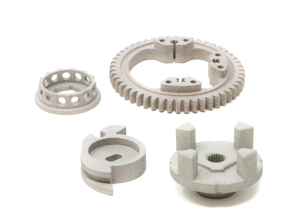
TriTech Titanium Parts LLC, a Detroit-based manufacturer of titanium parts for aerospace, marine, and automotive industries, and Desktop Metal, Inc., a global leader in additive manufacturing technologies for mass production, have announced the customer-qualification of Ti64 for binder jet 3D printing on the Production System™. The high-speed Single Pass Jetting (SPJ) technology platform features two models: the P-1, for research and development of binder jetting projects for serial production, and the P-50, the world’s fastest metal binder jet system, offering the lowest cost per part with SPJ technology. Ti64 is a popular material, known for its excellent strength-to-weight ratio, corrosion resistance, and biocompatibility. Binder jetting of Ti64 simplifies the production of complex titanium parts, which can be challenging and expensive to fabricate using traditional manufacturing methods.
Desktop Metal Production System via Desktop Metal
TriTech Titanium Parts LLC, which is ISO 9001:2015 certified, uses metal injection molding (MIM), investment casting, and now binder jet 3D printing on the Desktop Metal Production System P-1 to produce titanium parts. The company is a spin-off of AmeriTi Manufacturing Co., which was founded in 1984 and sold last year to Kymera International.
TriTech’s owner, Robert Swenson, who is also the former owner of AmeriTi, stated that with binder jet 3D printing, titanium production of even the most complex geometries can be greatly simplified and achieved at a lower cost. Swenson, a graduate of Purdue University with a degree in Metallurgical Engineering and an MBA from Harvard Business School, is incredibly proud to be the first Desktop Metal Production System P-1 customer worldwide to binder jet 3D print titanium, and the company is excited to offer this new manufacturing technology to its customers.
With the latest addition to the material portfolio, Desktop Metal offers the ability to binder jet 23 metals, including copper, aluminum, and now, titanium. Ric Fulop, Founder and CEO of Desktop Metal, stated that they are excited to help engineers and manufacturers produce complex, once-impossible designs in a wide range of metals, including challenging materials such as titanium.
While Ti64 is a popular material, it’s also known for being expensive to manufacture. The material’s strength, as well as its low thermal conductivity and ductility, make it challenging to machine or produce with traditional manufacturing methods. Shaping the material with MIM requires special knowledge and processes. TriTech is among a very small percentage of companies that produce titanium parts with MIM, and the company has developed its own MIM processes after years of R&D. However, with binder jetting, the process can be simplified and made more economical.
Binder jetting is a process where an industrial printhead selectively deposits a binder into a bed of Ti64 powder particles, creating a solid part one thin layer at a time, just like printing on sheets of paper. The form or shape produced by the printer is then sintered to high density and accuracy in a furnace, similar to the MIM process. Additionally, binder jetting allows unbound material to be reused in the process, adding to its cost efficiency.
Desktop Metal’s binder jet technology can 3D print almost any powder, which is why the company has a tiered material qualification system for metals to signify the varying levels of material property results produced by. Production System users interested in working with titanium should consult their Desktop Metal sales representative on hardware and binder requirements.
TriTech will discuss its experience binder jetting Ti64 at AMUG 2023, held March 19-23 in Chicago. The topic will be part of a Desktop Metal panel discussion from 1:30-2:30 p.m. Thursday, March 23,