This older article has been merged into Addithive’s updated pillar guide to avoid duplicate and conflicting explanations. The new guide covers the seven additive manufacturing process categories, the difference between 3D printing and industrial AM, a practical beginner workflow, material and process selection, applications, limitations and sustainability.
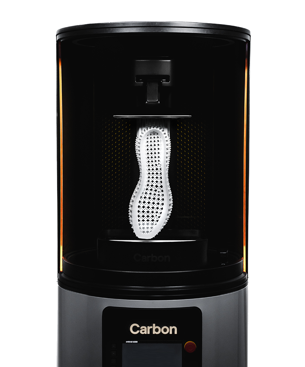
Carbon, the world’s leading 3D printing technology company, has announced its latest solution for clear aligner manufacturers that could revolutionize the industry. The Carbon® Gen 2 aligner model solution promises to bring efficiencies to the production process, enabling significant cost advantages and up to 65% increase in throughput, with less material required per print. This sustainable production solution, announced at the IDS conference in Cologne, Germany, includes new proprietary software and high-performance resin that integrate with Carbon’s existing printer hardware and aligner model workflow.
Carbon L1 3d Printer via Carbon3d
The Gen 2 aligner model solution is designed to offer new and existing customers integration with Carbon’s existing clear aligner workflow, which is already used by leading aligner manufacturers to produce millions of custom clear aligners worldwide each month. The solution includes the Carbon L1 printer, solventless spin cleaning solution, and API-based software that automates the hollowing, nesting, and batching of models to be printed. The new UMA 20 resin, engineered in parallel with Carbon’s new production solution, automatically hollows models, a revolutionary approach that creates a cost-effective and sustainable solution for clear aligner manufacturers.
One of the most exciting benefits of this new solution is the potential to reduce material consumption by up to 40% per model, while increasing throughput up to 65% with the Carbon L1 printer. This means aligner manufacturers can produce more aligners in less time, at a lower cost, without compromising quality. The automated hollowing software, paired with the UMA 20 resin, enables increased part throughput, making the production process more efficient and streamlined.
Another significant advantage of the Gen 2 aligner model solution is improved sustainability. The solution features improved solvent-free model cleaning, which eliminates solvent waste and allows resin to be reclaimed for future use. Aligner manufacturers can save money and reduce their environmental footprint by using this more sustainable production process.
Carbon 3d
Terri Capriolo, Senior Vice President, Oral Health at Carbon, spoke about the new solution, saying, “Working with the top clear aligner companies has given us insight into the barriers this industry faces on a daily basis. We heard from customers and we took action to create efficiencies and cost savings in the clear aligner workflow. This new aligner workflow is designed to enable Carbon customers to reduce cost per part while simultaneously improving model throughput with a more sustainable production process.”
The Carbon® Gen 2 aligner model solution will be available to customers in the second half of 2023. It will be showcased at the IDS Conference, a leading global trade fair for the dental community, which took place in Cologne from March 14-18, 2023. Aligner manufacturers can learn more about the solution and its benefits by visiting the Carbon website.
Overall, the Carbon® Gen 2 aligner model solution is an exciting development for the clear aligner industry. The ability to produce more aligners in less time, at a lower cost, while also reducing material consumption and improving sustainability, makes this solution a game-changer. Carbon continues to innovate and push the boundaries of 3D printing technology, and we can’t wait to see what they come up with next.
Additive manufacturing software is not a single application. Industrial AM depends on a connected toolchain that can preserve design intent, prepare the build, simulate process risk, communicate with equipment, schedule production, capture quality data and maintain traceability.
The best AM software stack is not the one with the longest feature list. It is the one that creates a controlled path from released design to accepted part.
The additive manufacturing software stack
Layer
Main job
Typical outputs
Requirements and PLM
Control product definition, revisions and approvals
Released CAD, drawing, specification and configuration
DfAM and computational design
Create manufacturable geometry that uses AM effectively
Topology-optimized parts, lattices, channels and design variants
Data preparation and repair
Validate and transform geometry for production
Repaired mesh or manufacturing geometry
Build preparation
Orient, support, nest and slice parts
Released build layout and machine-ready job
Process simulation
Predict distortion, thermal history or process risk
Compensated geometry, risk maps and process recommendations
Machine and build processor
Translate the job into equipment-specific instructions
Scan paths, exposure strategy and machine file
MES and production management
Schedule orders, resources and work steps
Travelers, capacity plan and work-in-process status
Monitoring and telemetry
Capture machine state and process signals
Layer images, alarms, sensor data and event logs
Quality and inspection
Connect measurements and nonconformances to the part
Inspection reports, CAPA, disposition and release evidence
Analytics and costing
Measure yield, throughput, cost and bottlenecks
Accepted-part cost, utilization and improvement priorities
1. Requirements, CAD and product lifecycle management
The workflow should begin with an authoritative product definition. CAD and PLM systems control part number, revision, material, critical characteristics and approvals. AM-specific tools should consume this released definition without creating uncontrolled copies.
Native CAD is preferable when complex features, assemblies, tolerances or design history must remain editable. Tessellated files such as STL can still be useful, but they discard much of the original design intelligence and can create resolution, unit and repair problems.
2. DfAM and computational design
Traditional CAD is effective for conventional geometry, but lattices, field-driven structures and highly complex thermal or fluid designs can require implicit or computational methods. Typical capabilities include:
Topology optimization and generative exploration
Lattice and cellular structures
Conformal channels and heat exchangers
Field-driven variation of thickness, density or feature size
Automated design families and mass customization
Manufacturing-constraint checks
Examples include integrated CAD platforms such as Siemens NX and Dassault Systèmes solutions, as well as computational design tools such as nTop. The selection should depend on geometry complexity, parameterization, simulation integration and the ability to transfer the design without losing fidelity.
3. Data preparation and geometry repair
Before a part enters build preparation, the software should identify open edges, inverted normals, self-intersections, thin regions, disconnected bodies and other geometry problems. Repair automation is useful, but every automatic change should be reviewable because it can alter design intent.
Materialise Magics remains a prominent example of dedicated data and build-preparation software. Autodesk Netfabb, 3DXpert and integrated CAD/CAM platforms also provide geometry-preparation functions. Compatibility should be confirmed for the exact process, machine and build processor rather than assumed from a generic feature list.
4. Build preparation
Build preparation converts a valid part into a manufacturing configuration. It typically includes:
Machine and build-volume selection
Orientation and placement
Support generation
Nesting and collision checks
Machining allowance and sacrificial features
Coupon and witness-specimen layout
Slicing and scan-vector generation
Estimated build time and material use
Orientation should not be optimized only for print time. It affects support removal, residual stress, anisotropy, surface condition, powder escape, machining and inspection access.
5. Process simulation
Simulation can reduce physical iteration by estimating distortion, recoater risk, support loading, thermal accumulation or residual stress. Different models serve different decisions:
Simulation level
Typical use
Main limitation
Fast inherent-strain or reduced-order model
Orientation, support and distortion screening
Requires calibration and simplifies local physics
Layer or path-level thermal model
Thermal history and local process analysis
High computation and data demand
Material or sintering model
Binder-jet shrinkage, distortion and setter design
Depends strongly on feedstock and furnace calibration
Structural performance simulation
Verify the final design under service loads
Needs representative material and defect assumptions
Examples include Simufact Additive, Autodesk Netfabb Local Simulation, Siemens integrated simulation and other process-specific tools. Simulation should be validated against coupons and representative parts before it is used for release decisions.
6. Build processors and machine connectivity
A build processor is the controlled interface between general build preparation and a specific machine platform. It may define exposure strategies, scan paths, parameter assignment and job transfer. Machine connectivity can be direct, through an OEM application, or through an approved partner integration.
EOSPRINT, Materialise Build Processors, Siemens machine kits and OEM software are examples of this layer. The critical questions are not only whether a file can be exported, but whether the approved parameter set, software version and machine configuration remain traceable.
7. MES, order management and the digital thread
As production grows, spreadsheets and shared folders become weak controls. AM-focused MES and workflow platforms can manage:
Order intake and technical review
Routing through printing, heat treatment, machining and inspection
Machine, furnace and labor capacity
Material-lot and powder-reuse history
Traveler execution and electronic signatures
Nonconformance and corrective action
Part-level genealogy and release records
Materialise CO-AM is one current example of a platform connecting order management, MES, machine telemetry, quality and analytics. General PLM, MES and QMS systems can also support AM when their data model captures AM-specific configuration and genealogy.
8. Monitoring, quality and inspection software
Machine monitoring software can collect layer images, melt-pool signals, recoater events, oxygen history, temperatures and alarms. These signals are valuable only when they are linked to machine, build, layer, part location and a validated decision rule.
Quality software should connect inspection plans, metrology results, NDT, material testing and deviations to the same part identity. Monitoring data does not automatically replace part inspection; it can support process understanding and risk-based acceptance only after correlation has been demonstrated.
9. Costing and production analytics
A useful costing model extends beyond machine hours. It should include:
Engineering and build-preparation labor
Material, supports, powder refresh and scrap
Machine, gas, energy and maintenance
Heat treatment, HIP, sintering and furnace occupancy
Support removal, machining and surface finishing
Inspection, documentation and rejected parts
Queue time and working capital
The most important metric is often cost per accepted finished part, not theoretical cost per build hour.
Current software examples by function
Function
Examples
Selection question
Integrated CAD and manufacturing
Siemens NX, Dassault Systèmes 3DEXPERIENCE/DELMIA
Can the organization keep native design, build preparation and post-processing in one controlled environment?
Computational DfAM
nTop and integrated generative-design tools
Can it handle the required lattices, fields and automated variants without fragile geometry?
Data and build preparation
Materialise Magics, Autodesk Netfabb, 3DXpert
Does it support the exact machines, support strategies and file-control requirements?
Process simulation
Simufact Additive, Netfabb Local Simulation and platform-specific simulation
Has the model been calibrated for the alloy, machine and route?
Machine execution
EOSPRINT, OEM software and approved build processors
How are parameters and software versions released and traced?
MES and digital thread
Materialise CO-AM and configured enterprise MES/PLM/QMS platforms
Can the system connect all downstream operations and part genealogy?
Software ownership and product strategy can change. Verify current licensing, support, cybersecurity, export-control and product-roadmap status before making a long-term platform decision.
How to select an AM software stack
Map the workflow. Document every transformation from released CAD through part acceptance.
Define authoritative systems. Decide where design, manufacturing, material and quality records are controlled.
List exact equipment. Check compatibility with machine models, firmware, build processors and inspection systems.
Test representative complexity. Use a real lattice, large build, support strategy and downstream route rather than a demonstration cube.
Measure interoperability. Record where geometry, metadata or parameters are lost between tools.
Validate simulation and automation. Compare software predictions with physical results.
Model total ownership cost. Include licenses, modules, APIs, training, customization, upgrades and support.
Review cybersecurity and retention. Protect IP and ensure records remain readable over the required life.
Run a controlled pilot. Measure preparation time, first-pass yield, traceability and accepted-part lead time.
Common implementation mistakes
Selecting software from screenshots rather than production workflows
Assuming one application can replace PLM, MES, QMS and machine software
Using STL as the only long-term product definition
Automating an unstable manual process
Ignoring post-processing, inspection and supplier data
Allowing machine files or parameters to remain on local computers without revision control
Buying simulation without a calibration and validation plan
Measuring printer utilization while ignoring accepted-part throughput
Conclusion
Industrial additive manufacturing software should be designed as a connected architecture rather than a list of standalone products. Start with requirements and configuration control, then select the smallest set of tools that can preserve design intent, execute the approved route and produce trustworthy acceptance evidence.
Desktop Metal, in partnership with Sandvik Additive Manufacturing and a top five global automaker, has announced that copper alloy C18150, also known as chromium zirconium copper, has been DM Qualified for binder jet 3D printing on the Production System. This material is commonly used in electrical and electronic components due to its high-strength and high-conductivity properties. The automaker is testing a unique 3D printed part design, which is being developed for a future production application, in C18150 using Sandvik’s Osprey metal powder. The companies will discuss details of this joint automotive project during a presentation at AMUG 2023 in Chicago. With the addition of C18150, Desktop Metal now offers a world-leading 23 metal materials on its binder jet 3D printing systems, including the Shop System, Production System, and X-Series platforms.
Chromium zirconium copper offers a combination of strength, conductivity, and corrosion resistance that makes it suitable for a wide range of industrial and commercial applications. The material has now been qualified for use on the high-speed Printing System platform in collaboration with Sandvik Additive Manufacturing, who provided C18150 powder that routinely delivered as-sintered densities of 98-99% when printed on the P-1. The automaker will scale a part design in C18150 for serial production on the Production System P-50 after additional development.
Chromium zirconium copper parts via Desktop Metal
Desktop Metal’s founder and CEO, Ric Fulop, expressed pride in announcing the qualification of chromium zirconium copper as a qualified material, bringing the company’s world-leading portfolio of binder jet materials to 23 metals. He also highlighted the simultaneous announcement of 304L qualification on the Shop System and Ti64 customer-qualification on the Production System. The company’s experts are collaborating with customers on application-specific material and part qualification projects for future Additive Manufacturing 2.0 production.
Desktop Metal Production System
Desktop Metal’s binder jet technology can 3D print almost any powder. The company has a tiered material qualification system for metals to signify the varying levels of material property results produced by its technology. DM Qualified signifies printing and sintering profiles developed by DM, with fully characterized material and mechanical properties that meet MPIF or other similar standards where available. Customer-Qualified materials have been qualified by customers with their own standards and are being successfully printed for their own applications. R&D Materials signify initial testing completed by DM demonstrating binder and process compatibility, with printing and sintering profiles under final development.
The Production System platform features high-speed Single Pass Jetting (SPJ) technology on two models: the P-1, for research and development of binder jetting projects for serial production, and the P-50, the world’s fastest metal binder jet system, offering the lowest cost per part, with SPJ technology. With C18150 qualification, the Production System now offers a wider range of options for customers seeking to use copper alloys in their products.
Desktop Metal and Sandvik will provide an update on binder jetting of Ti64 and Al6061 at AMUG 2023. The companies will also discuss details of the automotive project during a panel discussion from 1:30-2:30 p.m. on Thursday, March 23, in the Joliet Room at the Hilton Chicago.
In conclusion, Desktop Metal’s qualification of copper alloy C18150 for binder jet 3D printing on the Production System, in collaboration with Sandvik Additive Manufacturing and a top five global automaker, represents a significant milestone in the company’s efforts to provide a world-leading portfolio of binder jet materials to its customers. The partnership has demonstrated the capabilities of binder jetting in the production of complex parts in copper alloys, opening up a range of applications in thermal transfer and other
Addithive’s explanation of “3D printing” versus “additive manufacturing” now appears inside the complete introduction to additive manufacturing. The terms describe the same underlying family of material-addition technologies; the practical difference is usually context. “3D printing” is common in desktop and public-facing use, while “additive manufacturing” more often describes an industrial production system.
Nondestructive testing (NDT) is essential for additive manufacturing, but no single method can guarantee that a complex AM part is defect-free. Inspection capability depends on the process, alloy, geometry, surface condition, defect type, defect orientation, required resolution and acceptance criteria.
The correct question is not “Which NDT method is best for AM?” It is “Which combination of methods can detect the credible defects in this specific part with the required probability of detection?”
Why AM inspection is different
Metal additive manufacturing can produce internal channels, lattices, thin walls and highly integrated geometries that are difficult to inspect using methods developed for simple wrought or machined parts. AM defects can also be small, irregular, directionally oriented and distributed differently across the build.
Inspection planning therefore begins with the complete manufacturing route: feedstock, machine, process parameters, build orientation, heat treatment, hot isostatic pressing, machining and surface finishing. Post-processing can close, reveal, reshape or remove indications, so the inspection stage matters.
Common defect and imperfection classes
Imperfection
Typical cause
Inspection challenge
Lack of fusion
Insufficient energy, poor overlap, contamination or unstable powder layer
Often planar and orientation-sensitive
Gas porosity
Entrapped gas, powder condition or melt-pool behavior
Small rounded pores may require high volumetric resolution
Keyhole porosity
Excessive energy density and unstable deep melt pool
May appear as irregular or elongated pores
Cracks
Residual stress, hot cracking, thermal cycling or alloy sensitivity
Thin planar cracks can be difficult to detect when poorly oriented to the inspection beam
Inclusions or contamination
Foreign material, oxide, spatter or handling contamination
Detectability depends on density contrast and size
Dimensional deviation
Shrinkage, distortion, support failure, thermal behavior or post-processing
Internal geometry may be inaccessible to conventional metrology
Surface-connected discontinuities
Support removal, machining damage, cracking or incomplete fusion
Rough as-built surfaces can create false or masked indications
Trapped powder
Insufficient escape paths or ineffective cleaning
May be hidden inside channels and cavities
X-ray computed tomography
Industrial X-ray computed tomography (CT) is one of the most powerful tools for AM because it can reconstruct internal and external geometry in three dimensions. It can detect porosity, lack-of-fusion regions, inclusions, dimensional deviations, trapped powder and inaccessible internal features.
CT is not unlimited. Detectability depends on voxel size, focal spot, detector, material density, wall thickness, part diameter, scan geometry, reconstruction and analysis settings. A large dense nickel-alloy part cannot be inspected at the same resolution as a small aluminum coupon. CT resolution claims must be connected to the actual part and minimum defect size.
Strengths: volumetric data, internal geometry, pore distribution and dimensional comparison.
Limitations: cost, scan time, penetration, artifacts, resolution versus part size and interpretation complexity.
Best practice: validate the technique using representative artifacts or seeded flaws and document the scan and analysis parameters.
Conventional radiography
Two-dimensional radiography can detect volumetric discontinuities and density variations, but it compresses three-dimensional information into a projection. Overlapping features and complex geometry can mask defects. Planar flaws aligned unfavorably to the beam may be difficult to see.
Radiographic testing
Ultrasonic testing
Ultrasonic testing can detect internal cracks, lack of fusion and other discontinuities in suitable geometries. Phased-array and advanced full-matrix techniques can improve coverage and imaging. However, rough surfaces, thin sections, complex curvature, internal channels and anisotropic microstructures can complicate coupling, wave propagation and signal interpretation.
Machined inspection surfaces or purpose-designed access may be needed. Calibration blocks and reference reflectors should represent the alloy, heat treatment, geometry and expected defect orientation as closely as practical.
Liquid penetrant testing
Liquid penetrant testing is effective for surface-breaking discontinuities on nonporous, clean surfaces. As-built AM roughness can retain penetrant and generate excessive background. The method is often more reliable after machining or surface finishing, when the inspection surface and cleaning process are controlled.
Penetrant testing cannot detect sealed internal defects and should not be treated as evidence of volumetric integrity.
Magnetic particle testing
Magnetic particle testing can reveal surface and near-surface discontinuities in ferromagnetic alloys. It is not applicable to titanium, aluminum, austenitic stainless steels or most nickel alloys. Surface roughness, geometry and residual magnetism must be controlled.
Eddy current testing
Eddy current methods detect surface and near-surface discontinuities in electrically conductive materials. They can be sensitive to small cracks, but probe access, lift-off, curvature, roughness, conductivity variation and geometry affect performance. Eddy current inspection is generally local rather than a complete volumetric method.
Optical and dimensional inspection
Coordinate measuring machines, structured-light scanners, laser scanners and optical microscopy verify dimensional and surface requirements. They do not replace volumetric NDT. Line-of-sight systems cannot measure hidden channels, and highly reflective or rough surfaces may require preparation or specialized scanning strategies.
In-situ monitoring is not final NDT
Melt-pool sensors, layer imaging, recoater monitoring, acoustic signals and machine logs can identify process anomalies. These data improve traceability and may support adaptive control. However, an anomaly signal is not automatically a verified defect, and the absence of an alarm does not prove that the part is acceptable.
In-situ monitoring must be correlated with destructive testing, NDT and production outcomes before it can support acceptance decisions. It is best viewed as one layer in a broader process-control and inspection strategy.
Probability of detection and validation
A method may detect a large laboratory defect without reliably detecting the smallest critical defect in production. For safety-critical applications, inspection capability should be demonstrated using representative part thickness, geometry, alloy, surface condition and defect type.
Define the minimum relevant defect size and orientation.
Use representative reference standards, test artifacts or intentionally seeded flaws.
Control equipment, calibration, software, analysis thresholds and operator qualification.
Document false-call risk and inspection blind zones.
Revalidate the method when geometry, material, surface or equipment changes materially.
How to build an AM inspection plan
Identify critical functions and credible failure modes.
Map likely imperfection types to the AM process and post-processing route.
Define inspection zones and required detection capability.
Select complementary surface, dimensional and volumetric methods.
Design inspection access into the part where possible.
Validate methods on representative artifacts or seeded flaws.
Set acceptance criteria based on engineering significance, not merely visibility.
Link results to build records, material genealogy and configuration control.
Quick method comparison
Method
Best at
Main limitation in AM
X-ray CT
Internal geometry and volumetric defects
Resolution, penetration, artifacts, cost and part-size trade-off
Radiography
Volumetric density changes in suitable geometries
Feature overlap and limited 3D localization
Ultrasonic testing
Internal cracks and planar defects with suitable access
Rough surfaces, complex geometry and anisotropic propagation
Liquid penetrant
Surface-breaking defects
As-built roughness and no subsurface capability
Magnetic particle
Surface/near-surface defects in ferromagnetic materials
Material limitation and surface sensitivity
Eddy current
Small surface/near-surface cracks in conductive materials
Local access, lift-off and geometry sensitivity
Optical/CMM
External dimensions and visible surface condition
No internal volumetric capability
In-situ monitoring
Process anomalies and traceability
Requires correlation; not direct proof of final part integrity
Conclusion
Reliable AM inspection combines process knowledge, complementary NDT methods and validated detection capability. Complex geometry does not make a part uninspectable by definition, but it can create blind zones that must be understood during design. The inspection plan should be developed with the part and manufacturing route, not added after printing.
The digital thread in additive manufacturing is the controlled connection between product definition, manufacturing configuration, process data, inspection evidence and final part identity. Its purpose is not to collect every available signal. It is to preserve enough trusted information to reproduce, investigate and release the part.
A useful digital thread answers four questions: What was authorized? What was actually used? What happened during production? What evidence supports acceptance?
Why additive manufacturing needs a strong digital thread
AM relies on a dense chain of digital and physical transformations. A CAD model is converted into manufacturing geometry, oriented, supported, nested, sliced and translated into machine instructions. Feedstock, machine condition, software, parameters, heat treatment, machining and inspection then determine the final hardware.
If these relationships are not controlled, two parts with the same nominal drawing can be produced through materially different routes. That undermines repeatability, root-cause analysis, supplier transfer and qualification.
Digital thread, digital twin and data package are not the same
Concept
Practical meaning in AM
Primary purpose
Digital thread
Traceable information flow across design, manufacturing, inspection and service
Configuration continuity and provenance
Digital twin
A digital representation connected to a physical asset or process through data exchange
Monitoring, prediction, simulation or decision support
AM data package
A defined set of information associated with a specific part or manufacturing workflow
Communication, acceptance, retention and auditability
Machine log
Equipment-generated operational and event records
Process traceability and troubleshooting
Build file
Manufacturing representation used to execute a specific build
Machine execution; not by itself a complete production record
A company can have a digital thread without a sophisticated real-time digital twin. It can also have large volumes of machine data without having a trustworthy digital thread.
The core objects that must be connected
1. Product definition
Authoritative CAD model and drawing
Part number, revision and effectivity
Material and process specifications
Critical characteristics and acceptance criteria
Approved deviations, concessions and repairs
2. Manufacturing definition
Orientation, support and nesting configuration
Manufacturing geometry and file format
Machine model and machine identity
Software, slicer and parameter-set versions
Build plate, substrate or fixture definition
Coupon and witness-specimen layout
3. Material genealogy
Powder, wire, resin or bound-feedstock lot
Supplier certificate and incoming inspection
Storage, handling and environmental history
Powder reuse, blending, sieving and refresh history
Contamination or disposition records
4. Process execution
Build start and completion information
Machine state, alarms and operator interventions
Atmosphere, temperature and other controlled conditions
Layer images, recoater events or melt-pool data where required
Maintenance and calibration status
Nonconformance and interruption records
5. Post-processing history
Stress relief, heat treatment and HIP cycles
Debinding and sintering records
Build-plate and support-removal route
Machining programs, fixtures and completed operations
Surface finishing, coating and cleaning
Subcontractor certificates and process records
6. Inspection and acceptance
Dimensional results and inspection-program revision
NDT equipment, technique and operator identity
Material test results and specimen location
Cleanliness, flow or functional-test results
Disposition and final release authorization
Link between the physical serial number and digital record
The authoritative-source problem
AM workflows often create multiple copies of geometry and parameters across PLM, CAD, build-preparation software, local workstations and machine controllers. A valid digital thread must identify which object is authoritative and which copies are derived.
Useful controls include:
Unique identifiers and revision status
Checksum or cryptographic hash for critical files
Role-based approval and electronic signature
Controlled transfer from engineering to manufacturing
Read-only released records
Documented regeneration rules when a derived file changes
Saving a file with “final” in its name is not configuration control.
Machine data: collect what supports a decision
Modern AM machines can generate large amounts of data. Storage volume is not the same as traceability value. Before collecting a signal, define:
Which failure mode or quality characteristic it represents
How the sensor is calibrated and time-synchronized
How the data is linked to machine, build, layer and part location
Which limits, alerts or analysis methods are approved
How long the data must be retained
Who can modify, interpret and disposition the record
ISO/ASTM 52953:2025 establishes minimum requirements for registering multimodal monitoring and quality-control data. The emerging direction is toward structured, referenceable data rather than isolated screenshots and proprietary reports.
The 2026 data-package standard
ISO/ASTM 52951:2026 provides a framework for developing and using AM part data packages from design through acceptance. It is based primarily on PBF-LB/M, but its workflow principles can inform other AM processes.
The practical significance is that organizations can define data-package depth by part class, customer need and regulatory risk. A prototype bracket should not require the same evidence as a flight-critical component, but both should have a clear minimum record.
Cybersecurity and intellectual property
The digital thread can expose design IP, process know-how and evidence used for certification. Security should be designed into the workflow rather than added after deployment.
Apply least-privilege access and strong identity management.
Separate development, production and supplier environments where appropriate.
Encrypt sensitive data in transit and at rest.
Record file transfers, approvals and administrative actions.
Control removable media and machine-network interfaces.
Validate backup, recovery and long-term readability.
Define which supplier data must be shared and which can remain protected.
Blockchain is not a prerequisite for trustworthy AM traceability. In most factories, disciplined configuration management, access control, audit logs and signed records create more immediate value.
Interoperability remains a bottleneck
AM data can pass through CAD, PLM, MES, QMS, build-preparation tools, machine software, laboratory systems and supplier portals. Proprietary formats and inconsistent naming make it difficult to connect the record.
Organizations should define stable identifiers, metadata and interfaces even when full automation is not possible. A controlled manual link is better than an invisible automated transformation that cannot be audited.
A practical minimum viable digital thread
Give every part, build and material lot a unique identifier.
Control the released product definition and manufacturing revision.
Link orientation, support, nesting, machine and parameter configuration.
Record feedstock genealogy and equipment readiness.
Capture alarms, deviations and operator interventions.
Link post-processing records to the serial number or production batch.
Store inspection results with technique and acceptance criteria.
Protect approved records from uncontrolled modification.
Define retention, backup and migration rules.
Test whether the organization can reconstruct the complete history of a released part.
Common failure modes
Machine files stored only on a local workstation
Parameters renamed without version or approval history
Powder lots blended without genealogy
Inspection reports disconnected from the physical part identity
Large monitoring-data archives with no validated interpretation
Supplier records delivered as unsearchable PDFs with ambiguous references
Software updates applied without configuration review
Digital records that cannot be opened years later
Conclusion
The AM digital thread is a quality and configuration system, not a marketing layer. Its value comes from connecting authorized design, actual manufacturing conditions and acceptance evidence to a specific physical part. Start with traceability and decision needs, then add automation, analytics and digital-twin capability where they solve a defined problem.
Additive manufacturing (AM) creates a physical part directly from digital data by adding material in successive layers or deposits. The familiar term 3D printing is often used interchangeably, but in industrial settings additive manufacturing usually refers to the complete production system: design, build preparation, printing, post-processing, inspection, qualification and configuration control.
The important question is not whether a part can be printed. It is whether the complete manufacturing route can deliver the required performance, cost, lead time and repeatability.
What additive manufacturing is — and what it is not
AM differs from subtractive processes such as machining, which remove material, and formative processes such as casting, forging or molding, which shape material using a tool or die. That distinction does not make AM automatically better. Most production parts still require a hybrid route that combines printing with heat treatment, support removal, machining, surface finishing and inspection.
AM is most valuable when it changes the economics or performance of a product. Typical value drivers include part consolidation, internal channels, lightweight structures, patient-specific geometry, rapid design iteration, digital inventory, low-volume production and repair of high-value components.
The seven main additive manufacturing process categories
ISO/ASTM terminology groups additive manufacturing into seven broad process categories. Commercial names vary by supplier, so the process category is usually the clearest starting point.
Repair, feature addition, large near-net-shape components
Sheet lamination
Sheets are bonded and cut into shape
Paper, polymers, metals
Visual models, tooling and specialized metal laminates
How the industrial AM workflow works
Define the requirement. Start with loads, environment, life, tolerances, surface condition, regulatory requirements and production volume — not with a preferred printer.
Select the process and material route. The machine, feedstock, process parameters and post-processing route form one manufacturing system. A material name alone does not define performance.
Design for the process. Orientation, support strategy, minimum feature size, powder removal, machining allowance, inspection access and thermal behavior must be considered early.
Prepare and build. The digital model is converted into layers or toolpaths. Build preparation includes nesting, orientation, support generation, parameter selection and traceability controls.
Post-process. Depending on the route, this can include curing, depowdering, debinding, sintering, stress relief, hot isostatic pressing, support removal, machining and surface finishing.
Inspect and validate. Dimensional inspection, material testing and nondestructive evaluation are selected according to the failure modes and acceptance requirements.
Control the production system. Industrial AM requires qualified equipment, trained personnel, controlled feedstock, documented procedures and change management.
Where additive manufacturing creates the most value
Complex, high-value parts: The economic case improves when geometry, performance or part consolidation matters more than raw deposition speed.
Low-to-medium production volumes: AM avoids dedicated tooling and can shorten development cycles.
High buy-to-fly or buy-to-use ratios: Near-net-shape production can reduce the amount of expensive material removed during machining.
Customized products: Dental devices, implants, orthotics and specialized tooling benefit from digital variation without new hard tooling.
Supply-chain resilience: Qualified digital inventory can reduce dependence on slow or obsolete tooling, although certification and data control remain significant barriers.
Repair and feature addition: Directed energy deposition can restore high-value components or add local features to forged or machined substrates.
The limitations that matter in production
Post-processing is often the real bottleneck. Printing may be only one step in a long production route.
Material properties are process-route dependent. Orientation, machine condition, parameters, heat treatment and specimen location can change results.
Surface finish and tolerances are not automatically production-ready. Critical interfaces frequently require machining or finishing.
Qualification can dominate cost and schedule. Aerospace, medical and other safety-critical applications require evidence that the entire process is stable and repeatable.
Build failures are expensive. Long build times, high-value powder and limited machine availability increase the cost of nonconformance.
AM is not inherently sustainable. The environmental result depends on material yield, energy use, inert gas, post-processing, scrap, part life and the conventional route being displaced.
How to decide whether a part is a good AM candidate
A useful screening exercise asks five questions:
Does AM enable a geometry or performance improvement that conventional manufacturing cannot deliver economically?
Can multiple parts, welds or assembly operations be consolidated?
Is the annual volume compatible with the expected build rate, post-processing capacity and cost per part?
Is a qualified material and process route available for the required environment?
Can powder removal, support removal, machining and inspection be completed without creating hidden risk?
If the answer is mostly no, conventional manufacturing or a hybrid route may be the better choice. A successful AM program begins with process-neutral engineering and a complete cost model.
Additive manufacturing in aerospace, medical and industrial production
Aerospace applications emphasize weight reduction, thermal performance, part consolidation and high-value low-volume production. Medical and dental applications benefit from patient-specific geometry, porous structures and digital workflows. Industrial users increasingly apply AM to tooling, spare parts, heat exchangers, fluid systems and repair. In each sector, the durable advantage comes from integrating design, material science, process control and qualification — not from the printer alone.
3D printing vs additive manufacturing: is there a difference?
The terms are built on the same fundamental idea: creating a three-dimensional object by adding material from digital data. In everyday use, 3D printing often describes desktop machines, prototyping and the printing step itself. Additive manufacturing is more common in industrial environments, where the term includes the complete controlled route from design and feedstock through post-processing, inspection and part release.
This is primarily a difference in context, not a boundary between two separate technologies. A desktop material-extrusion machine is an additive manufacturing system, and an industrial metal LPBF machine also performs 3D printing. For clear technical communication, name the process category and material rather than relying on either umbrella term alone.
Context
Useful wording
Example
General public or hobby use
3D printing
Desktop FFF printing in PLA
Industrial production
Additive manufacturing
Qualified LPBF production of a metal component
Technical specification
Standardized process category
PBF-LB/M, material extrusion or vat photopolymerization
Supplier-specific discussion
Process plus platform or commercial name
Polymer SLS on a defined machine and material system
How a beginner should get started
The best starting point depends on whether the objective is learning, prototyping or industrial production. Do not begin by comparing printers. Begin with the part, material and result you need.
Define the first project. Choose a small, useful object with simple success criteria. A fixture, enclosure, visual model or replacement knob teaches more than an overly ambitious demonstration part.
Select the process by need. Desktop material extrusion is usually the most accessible route for durable prototypes and learning. Resin vat photopolymerization is attractive for fine detail but requires stricter chemical handling, washing and curing. Industrial metal and polymer systems normally require trained operators and controlled facilities.
Choose a suitable material. Match temperature, strength, stiffness, chemical exposure, UV resistance and safety to the application. A printable material is not automatically suitable for service.
Use or create a controlled model. Check dimensions, wall thicknesses, clearances, units and licensing. Repair mesh errors before slicing.
Prepare the build. Orientation, supports, layer height, infill, temperatures and speed affect quality. Start with a validated profile and change one variable at a time.
Print safely. Follow the equipment and material manufacturer’s ventilation, fire, electrical, powder, resin and personal-protection requirements. Do not treat all desktop materials as harmless.
Inspect the result. Measure critical dimensions, examine layer bonding and test the part under realistic loads before using it in a functional or safety-relevant application.
Record what worked. Save material lot, machine profile, orientation, settings and observed problems. Repeatability begins with a simple process record.
A basic desktop 3D-printing toolchain
Step
Typical tool
What to learn first
Model creation
CAD, sculpting software or a licensed model repository
Dimensions, units, watertight geometry and design intent
Build preparation
Slicer supplied by or compatible with the printer
Orientation, supports, layer height, walls and material profile
Material handling
Dry storage for filament; controlled storage and PPE for resin
Moisture, contamination, shelf life and safe handling
Printing
Material-extrusion or resin printer
First-layer quality, calibration and monitoring
Post-processing
Support tools, washing/curing equipment or simple finishing tools
Safe removal, cleaning and dimensional preservation
Verification
Calipers, visual checks and application-specific testing
Fit, distortion, defects and functional limits
For industrial adoption, the starting path is different: outsource representative parts, build DfAM and acceptance knowledge, identify a repeatable application pipeline, and only then decide whether internal equipment is justified.
Customization, efficiency and sustainability: the claims to test
Additive manufacturing can enable customization, reduce tooling and improve material utilization, but these benefits are not automatic.
Customization: Digital variation can avoid new hard tooling, but design validation, data preparation and quality control still create cost. Customization creates value when the variation matters to the user or product performance.
Efficiency: AM can shorten development cycles and consolidate assemblies. Printing may still be slower or more expensive than molding, casting, forging or machining at stable high volume.
Material use: Near-net-shape production can reduce machining waste, especially for expensive alloys. Supports, powder refresh, failed builds, machining stock and post-processing losses must be included.
Energy and emissions: Results depend on process energy, inert gas, furnaces, heat treatment, finishing, transport, product life and the conventional route being replaced. AM is not inherently low-carbon.
On-demand production: Digital inventory can reduce physical stock, but only when the process, material, data, equipment and approvals remain available when the part is needed.
New materials: AM can process specialized feedstocks and create unusual microstructures, but every new route requires material characterization, process control and application validation.
The correct comparison is a lifecycle and system-level assessment of the AM route against a defined alternative. Claims such as “zero waste,” “instant production” or “complexity is free” should be treated as marketing shortcuts rather than engineering conclusions.
Common beginner misconceptions
A downloaded model is not necessarily printable, dimensionally correct or licensed for commercial use.
Higher infill does not automatically create the strongest or most efficient part; walls, orientation, material and load direction matter.
A visually successful print is not automatically safe for pressure, food contact, medical, electrical or load-bearing service.
FDM/FFF, resin printing, polymer SLS and metal LPBF are different process systems with different materials, risks and design rules.
Post-processing and inspection are part of the manufacturing process, not optional cleanup.
Buying a more expensive machine does not replace application knowledge and process discipline.
Conclusion
Additive manufacturing is now a family of industrial processes rather than a single disruptive technology. Its strongest applications combine a clear product advantage with a realistic production route. Engineers should evaluate AM as a system: digital definition, feedstock, equipment, process parameters, post-processing, inspection and quality control all determine the final part.
As the aerospace manufacturing industry continues to soar to new heights, it is clear that the sector is one of the most advanced and sophisticated commercial manufacturing systems in existence. It’s an industry that is constantly pushing the boundaries of technology to build highly complex, safety-critical structures and parts. But, despite this, the industry is still largely reliant on human skill and dexterity during assembly.
There have been efforts to introduce automation into aerospace manufacturing, but the uptake has been relatively low. This begs the question: why? Some may point to the size of the parts or the need for extreme accuracy. However, as with any complex issue, the problems are multifaceted. There are many contradictions and unsettled aspects still to be resolved, and there are no clear-cut answers to the automation conundrum.
One of the biggest challenges facing the aerospace industry when it comes to automation is the complexity of the manufacturing process. It is not just a matter of automating one task or process; rather, it involves automating multiple tasks that require a high degree of precision and accuracy. Additionally, the parts and structures being built in aerospace manufacturing are often incredibly complex, with intricate geometries and shapes that can be difficult to manufacture using traditional techniques.
Another challenge facing the aerospace industry when it comes to automation is the need for flexibility. Aerospace manufacturing is a highly dynamic industry, with constantly changing requirements and specifications. As a result, manufacturers need to be able to quickly adapt and change their manufacturing processes to meet new demands. This can be difficult to achieve with automated systems, which are often rigid and inflexible.
Furthermore, the cost of implementing automation in aerospace manufacturing can be prohibitively high. The technology required to automate many of the manufacturing processes in aerospace is often expensive, and the initial investment can be significant. This cost can be further exacerbated by the need for specialized personnel to operate and maintain the automated systems.
Despite these challenges, there are compelling reasons for the aerospace industry to pursue automation. One of the most significant benefits of automation is the potential to increase efficiency and reduce costs. Automated systems can work faster and with greater precision than human operators, which can result in shorter production times and lower defect rates.
Another potential benefit of automation in aerospace manufacturing is improved safety. Human error is a leading cause of accidents in the aerospace industry, and automation can help to reduce the risk of accidents by eliminating the need for human operators in dangerous or hazardous situations.
Finally, automation can help to address the skills gap in the aerospace industry. The industry is facing a shortage of skilled workers, and automation can help to mitigate this issue by reducing the need for highly skilled personnel in certain areas of the manufacturing process.
So, what needs to be done to increase the uptake of automation in aerospace manufacturing? One potential solution is to focus on developing more flexible and adaptable automated systems. This would allow manufacturers to quickly adapt their manufacturing processes to meet changing requirements and specifications, without having to invest in new systems or equipment.
Another solution is to focus on reducing the cost of implementing automation in aerospace manufacturing. This could involve developing more affordable technologies or finding ways to reduce the costs associated with operating and maintaining automated systems.
Ultimately, the key to increasing the uptake of automation in aerospace manufacturing is to continue to innovate and develop new technologies that can address the unique challenges facing the industry. By working together, industry stakeholders can help to build a more efficient, safer, and sustainable aerospace manufacturing sector that can meet the demands of tomorrow.
In conclusion, while the aerospace manufacturing industry is one of the most advanced and sophisticated commercial manufacturing systems in existence, there is still much work to be done when it comes to automation. The challenges facing the industry are multifaceted, and there are no clear-cut answers to the automation conundrum. However, with a continued focus on innovation and collaboration, the aerospace industry
Additive Manufacturing, or 3D-printing, technology has been a significant advancement in the manufacturing industry, with one of its most frequently mentioned benefits being the ability to produce parts at the point of use. This technology allows for the downloading of a digital file and the creation of the part on-site, which has the potential to greatly compress supply chains, lead times, inventories, and design iterations for custom parts.
The mobility industry, including automobile, aerospace, and transportation sectors, is one that demands precision, high-quality, and cost-effective solutions. Additive Manufacturing technology, with its ability to create complex geometries, lightweight designs, and rapid prototyping, is uniquely suited to meet the demands of the mobility industry. However, the viability of this technology for production at the point of use is not universal and depends on several factors, such as size, materials, build time, manufacturing complexity, cost, and competing technologies.
For the mobility industry, one of the key challenges is the size of the parts that can be produced using Additive Manufacturing technology. This is due to the limited build volume of the printer, which can increase the build time and cost for larger parts. Additionally, the quality of the part may be compromised due to the limitations of the printing process, which may not be suitable for high-stress applications, such as those found in the mobility industry.
Another challenge for the mobility industry is the limited range of materials that can be used for Additive Manufacturing. Although the range of materials that can be used has expanded with advancements in materials science, the majority of Additive Manufacturing materials are limited to plastics and some metals. This may not be suitable for applications that require high-strength materials, such as those found in the aerospace or automotive industries.
Despite these challenges, the mobility industry is investing in Additive Manufacturing capacity for production at the point of use. One of the key benefits of this technology is the ability to reduce supply chain and inventory costs by producing parts on-site. Additionally, the ability to create complex geometries and lightweight designs can lead to a reduction in fuel consumption and emissions, which is crucial in the transportation industry.
Moreover, Additive Manufacturing technology can significantly reduce the design iterations required for custom parts, leading to a faster time-to-market for new products and an increase in the speed of innovation. For instance, automotive companies can use Additive Manufacturing technology to rapidly prototype and test new designs, which can reduce the time and cost associated with traditional manufacturing methods.
However, it is essential for companies in the mobility industry to evaluate the feasibility and benefits of Additive Manufacturing technology on a case-by-case basis. This requires a deep understanding of the technology and its capabilities, as well as an evaluation of the costs and benefits associated with using Additive Manufacturing technology for production at the point of use.
In conclusion, Additive Manufacturing technology is a significant advancement for the mobility industry, providing unique advantages such as the ability to produce parts at the point of use and reduce supply chain and inventory costs. However, the viability of this technology for production at the point of use is dependent on several factors, including the size and complexity of the part, the materials used, and the cost of the technology. Therefore, it is important for the mobility industry to carefully evaluate the feasibility and benefits of Additive Manufacturing technology for their specific needs.