Tag: additive manufacturing

  • Material Advancements: Enhancing 3D Printing Capabilities in Manufacturing

    Material Advancements: Enhancing 3D Printing Capabilities in Manufacturing

    When it comes to advanced manufacturing, additive manufacturing, or 3D printing, has been hailed as a game-changer, capable of revolutionizing various industries. This innovative technology has the potential to unleash an array of new possibilities, from creating complex hollow structures to optimizing part designs for enhanced performance. However, despite its promise, 3D printing has yet to reach its full potential, primarily due to the limitations in materials, cost, and scalability. In this blog post, we will delve into the challenges holding 3D printing back and explore the advancements required to overcome these obstacles.

    The Power of Additive Manufacturing:

    3D printing has opened doors to designs that were once deemed impossible, thanks to its ability to create intricate hollow structures. Designers can now integrate cooling channels directly into high-temperature parts such as turbine blades and rocket nozzles. Additionally, topology optimization allows for the generation of the perfect structure for any application, much like our hollow bones, enabling lightweight vehicles to gain even more performance.

    Furthermore, traditional manufacturing methods often involve machining parts from large blocks of raw materials, resulting in significant waste. In the aviation industry, this waste is measured by the buy-to-fly ratio, which compares the weight of the final part to the weight of the raw material it was manufactured from. With 3D printing, this waste can be significantly reduced, leading to decreased costs and a more sustainable manufacturing process.

    A prime example of the capabilities of 3D printing is the incredible aerospike rocket engine, which incorporates liquid cooling channels directly into the rocket nozzle’s interior. This optimized design results in a highly efficient rocket nozzle that can operate effectively at various altitudes.

    Additive Rocket Engine – NASA

    Challenges and Limitations

    Despite the numerous benefits and potential applications of 3D printing, several factors are holding it back from widespread adoption. One major issue is the cost. When plotting the price of a 3D printed part as a function of the number of parts created, it becomes apparent that the initial machine cost dominates the price, and scaling up requires the purchase of additional machines. This lack of economies of scale makes 3D printing less attractive for high-volume, low-cost applications.

    Another challenge lies in the material properties of 3D printed parts. With thousands of years of experience in traditional metal forging, we have developed a deep understanding of how manufacturing techniques affect a metal’s properties. However, additive manufacturing forces us to start from scratch, building up our knowledge of the material properties of 3D printed parts.

    A key area of research in this regard is improving the fatigue life of 3D printed metals. Fatigue life refers to the number of stress cycles a part can withstand before breaking. Compared to traditionally machined parts, 3D printed parts tend to have a shorter fatigue life, making them less suitable for critical applications such as aviation.

    3D Printed Turbine Blades with Cooling Channels – ORNL

    Research and Advancements in Additive Manufacturing Materials

    Alloy Development for Additive Manufacturing

    Researchers are working on developing new metal alloys specifically designed for additive manufacturing. These alloys aim to provide better material properties, such as improved strength, ductility, and fatigue life, compared to existing materials used in 3D printing. Companies like OXMET are focusing on creating novel metal alloys that are optimized for additive manufacturing, taking into account the unique challenges and opportunities of the technology.

    Researchers at HRL Laboratories have developed a new metal alloy specifically designed for 3D printing: a high-strength aluminum alloy called Al 6061. This material offers improved performance and reduced cracking compared to conventional aluminum alloys. Its successful development and implementation have opened up new possibilities for 3D printed aerospace, automotive, and structural components.

    GRCOP-84 Powder Development – NASA Glenn Research Center

    Post-processing Techniques

    Post-processing techniques, such as hot isostatic pressing, can help improve the fatigue life of 3D printed parts. These methods involve applying heat and pressure to the printed part, closing the pores and imperfections that can lead to crack growth and fatigue failure. Researchers are also exploring other post-processing methods, such as heat treatments, that could further enhance the material properties of 3D printed metals.

    Tailoring Laser Scan Strategies

    By adjusting the laser scan strategy during the 3D printing process, researchers have discovered that they can influence the internal grain structure of the printed metal. This, in turn, affects the material’s properties, such as strength and fatigue life. Different scan strategies, such as the island or helical patterns, are being investigated to optimize the material properties of 3D printed metals.

    One notable example of this research is a project undertaken by the Oak Ridge National Laboratory, where scientists are investigating how adjusting the laser’s speed and power can impact the material properties of 3D printed metals. Their findings could lead to the development of new techniques that improve the fatigue life of printed parts, making them suitable for more demanding applications such as aviation.

    Machine Learning and In-situ Monitoring

    Researchers are also exploring the use of machine learning and in-situ monitoring to optimize the 3D printing process. By using thermal cameras and other specialized sensors inside the build chamber, they can observe phenomena like pore formation and adjust the laser’s operation in real-time to maximize material properties. This approach has the potential to significantly improve the fatigue life and overall performance of 3D printed parts.

    Researchers at the Technical University of Munich have developed a method called “in-situ process monitoring” that uses high-speed cameras to observe and analyze the 3D printing process in real-time. This method helps identify and minimize imperfections, such as porosity or cracks, and optimize the internal crystal grain structures for improved material properties.

    Siemens has been working on a project that combines machine learning and 3D printing to optimize the laser scan strategies for additive manufacturing. By analyzing the data generated during the 3D printing process, the company’s machine learning algorithms can determine the optimal scan patterns and laser settings, resulting in parts with improved material properties and reduced defects.

    Multi-Material Printing and Hybrid Manufacturing

    The future of additive manufacturing will likely involve the ability to print with multiple materials simultaneously, opening up new possibilities for creating complex, multi-functional parts. Hybrid manufacturing, which combines additive manufacturing with traditional subtractive methods like CNC machining, is also an exciting development on the horizon. This approach offers the best of both worlds, enabling the creation of intricate, optimized designs through 3D printing while ensuring the final parts meet the highest standards of precision and surface finish.

    Conclusion

    While 3D printing may not be suitable for low-cost, high-volume parts, improving fatigue life and material properties could lead to its use in more specialized applications, such as aerospace and other high-performance industries. As research continues to optimize 3D printing techniques and materials, we can expect to see additive manufacturing play an increasingly important role in the future of manufacturing.

    The ongoing advancements in cost reduction and material property optimization are creating exciting opportunities for 3D printing. As the technology matures, we may soon see a shift from its current focus on prototyping to a more widespread use in various industries. From automotive to aerospace, 3D printing has the potential to revolutionize how we design and manufacture products. With continued research and innovation, the future of 3D printing looks incredibly promising, and it will undoubtedly continue to shape the manufacturing landscape for years to come.

  • 3D Printing Stocks in 2023 — Archived Investment List

    3D Printing Stocks in 2023 — Archived Investment List

    This 2023 stock list is no longer a current investment universe

    This article originally reviewed a group of additive manufacturing and 3D-printing stocks using information available in April 2023. It is now preserved as a historical market snapshot.

    Several companies in the original list were acquired, taken private, delisted, restructured or materially changed their additive-manufacturing exposure. The original descriptions and ticker references should not be used for current investment decisions.

    Examples of changes since publication

    Company from the original articleMaterial change after the 2023 snapshot
    SLM SolutionsNikon completed the squeeze-out and made Nikon SLM Solutions a wholly owned subsidiary in 2023; it is no longer a standalone public AM stock.
    Fathom Digital ManufacturingCORE Industrial Partners completed a take-private acquisition in 2024.
    Desktop MetalNano Dimension completed the acquisition in April 2025. Nano Dimension later reported Desktop Metal in discontinued operations following bankruptcy and deconsolidation.
    MarkforgedNano Dimension completed the acquisition in April 2025 and announced an agreement in May 2026 to sell Markforged to Stratasys.
    Nano DimensionThe company’s investment case and AM asset structure changed substantially through acquisitions, divestiture plans and a proposed strategic combination.

    These examples are sufficient to make the original static list unsuitable as an evergreen investment guide. Current research must start from today’s ownership, listing, segment reporting and financial statements.

    Why “3D-printing stock” is an imprecise category

    The original article mixed several fundamentally different exposures:

    • Pure-play printer and materials companies
    • Digital manufacturing marketplaces and service bureaus
    • Software companies with limited AM revenue exposure
    • Diversified industrial companies with small AM divisions
    • Acquired companies that no longer trade independently
    • Companies whose primary value proposition changed after publication

    A better investment universe separates companies by business model, AM revenue exposure, value-chain role and ownership of an industrial bottleneck.

    The current Addithive classification

    BucketWhat it capturesPrimary investor question
    Core or pure-play AMCompanies whose economics depend heavily on additive manufacturingCan the platform reach durable margins and repeat production?
    Equipment and process platformsPrinter, deposition and production-system providersIs installed-base growth converting into recurring revenue?
    Materials and feedstockPowder, wire, polymer, resin and specialty-material suppliersDoes qualification create pricing power or switching cost?
    Software, simulation and digital threadDesign, build preparation, MES, monitoring and quality toolsHow material is AM to the wider software business?
    Services and digital manufacturingContract production and manufacturing marketplacesCan the business generate attractive utilization and gross margins?
    Post-processing and qualityHeat treatment, HIP, machining, metrology and inspectionDoes the company own a constraint that grows with AM adoption?
    Industrial adoptersAerospace, medical, dental, energy and automotive usersDoes AM create product or cost advantage large enough to affect earnings?

    What investors should verify now

    1. Current listing and ownership: Confirm ticker, exchange, parent company and transaction status.
    2. AM revenue exposure: Separate real AM sales from a broad advanced-manufacturing narrative.
    3. Revenue quality: Distinguish equipment shipments, services, consumables, software and recurring revenue.
    4. Installed-base economics: Measure utilization, service attachment and material pull-through.
    5. Cash and dilution: Review burn rate, financing needs and share issuance.
    6. Customer evidence: Look for qualified production and repeat orders rather than demonstrations.
    7. Gross margin and scale: Test whether growth improves economics or increases operating losses.
    8. Bottleneck ownership: Identify whether the company controls software, feedstock, post-processing, qualification or another scarce capability.
    9. Transaction risk: Account for acquisitions, asset sales, strategic reviews and delisting risk.
    10. Valuation: A useful AM technology does not automatically make an attractive stock.

    Current Addithive research

    Primary transaction references

    Archive status: This URL is retained for historical reference and existing external links. It is not investment advice or a current stock list.

  • Complex Parts in Additive Manufacturing: When Complexity Creates Value—and Risk

    Complex Parts in Additive Manufacturing: When Complexity Creates Value—and Risk

    Additive manufacturing can produce geometry that is difficult or impossible to make with conventional processes. But geometric complexity is not automatically valuable. Every internal channel, lattice, consolidated interface and unsupported feature can add design, build, cleaning, inspection, repair and qualification burden.

    Complexity is not free. AM changes where complexity is paid for—from shape-specific tooling into software, process control, post-processing and verification.

    The three types of complexity

    Complexity typeExamplesPotential valueTypical risk
    Geometric complexityInternal channels, lattices, undercuts, curved passages and topology-optimized shapesPerformance or weight improvementSupports, powder removal, distortion and inspection
    Functional complexityHeat exchange, fluid mixing, energy absorption, sensing or multiple functions in one bodyHigher system performanceHarder validation and coupled failure modes
    Organizational complexityMore software, suppliers, process steps, data and approvalsDigital flexibility and supply-chain redesignChange control, traceability and capability gaps

    A successful AM design reduces total system complexity even when the printed geometry becomes more complex.

    When complexity creates real value

    Internal flow and thermal geometry

    Conformal cooling channels, compact heat exchangers, fuel passages and mixing structures can create performance that drilled holes, brazed plates or cast cores cannot easily match. These are strong AM candidates when the internal surfaces can be cleaned, tested and manufactured repeatably.

    Part consolidation

    Combining several components can remove fasteners, welds, seals, inventory and assembly steps. Consolidation is valuable when it reduces system-level failure modes or cost. It is weak when it creates one expensive, unrepairable component from several simple serviceable parts.

    Topology optimization and lightweighting

    AM can place material along load paths and remove low-value mass. The resulting organic geometry can improve weight-sensitive systems, but it must preserve manufacturing access, minimum feature capability, fatigue performance and inspection.

    Lattices and cellular structures

    Lattices can provide stiffness-to-weight, energy absorption, thermal area, permeability or bone-ingrowth behavior. Their value depends on cell size, strut capability, surface condition, orientation and the ability to verify the internal structure.

    Mass customization

    Patient-matched medical devices, dental products, wearables and personalized tooling can vary geometry without new hard tooling. The manufacturing system must constrain customization within approved design rules.

    The complexity cost stack

    StageHow complexity adds cost
    DesignComputational geometry, optimization, simulation and more design iterations
    Data preparationLarge files, difficult meshes, orientation and support strategy
    PrintingLonger exposure paths, thermal accumulation, fragile features and higher failure consequence
    Material removalTrapped powder, resin, binder or support material
    Post-processingHard-to-reach supports, surfaces, heat-treatment distortion and special fixtures
    MachiningDifficult datums, limited tool access and interrupted cuts
    InspectionCT, advanced metrology, sectioning or indirect evidence
    QualificationMore worst-case locations, coupled features and process sensitivity
    ProductionLower yield and greater loss when one feature fails
    ServiceRepair, cleaning, maintenance and replacement of consolidated hardware

    Printability is only the first gate

    A part can be printable and still be unsuitable for production. A production-ready complex part must pass five gates:

    1. Buildable: It can be produced without unacceptable supports, collapse, distortion or thermal failure.
    2. Cleanable: Powder, resin, binder, support and processing debris can be removed.
    3. Finishable: Required surfaces can be machined, polished, coated or otherwise completed.
    4. Inspectable: Critical dimensions and defects can be verified with adequate probability of detection.
    5. Serviceable: The part can be assembled, maintained, repaired or economically replaced.

    Internal channels: the hidden challenge

    Internal channels are one of AM’s most valuable capabilities and one of its largest industrial risks. Review:

    • Minimum hydraulic diameter and aspect ratio
    • Self-supporting cross-section or internal supports
    • Powder or resin escape paths
    • Line-of-sight for cleaning or finishing
    • As-built roughness and pressure loss
    • Dimensional measurement method
    • Detection of blockage, lack of fusion or thin walls
    • Leak and pressure-test strategy
    • Repair or disposition if a channel fails inspection

    A channel should not be added merely because the printer can create it. It should provide enough thermal, fluid or assembly value to justify its lifecycle controls.

    Supports: geometry’s temporary tooling

    AM is often described as tool-free, but support structures can function as single-use tooling. They can:

    • Anchor the part
    • Conduct heat
    • Resist distortion
    • Support overhangs
    • Protect delicate features

    They also add material, build time, removal labor, surface damage and access requirements. Design complexity that demands inaccessible supports may be economically worse than a simpler conventionally manufactured geometry.

    Inspection is a design input

    NIST identifies complex surface topography, lattices, internal geometry, anisotropic properties and internal defects as major measurement and qualification challenges for AM. Inspection should therefore be selected while the geometry is still being designed.

    FeaturePossible inspection approachLimitation
    External geometryCMM, optical scanning or structured lightLine-of-sight and reflective or rough surfaces
    Internal channelsIndustrial CT, borescope, flow or pressure testPart size, material density and resolution
    Internal defectsCT, radiography or ultrasonic methodsDefect orientation, thickness and geometry
    Surface-connected defectsVisual, penetrant or magnetic methods where applicableRough surfaces can reduce sensitivity
    Lattice structureCT, mass, flow and representative destructive testingLarge data volume and limited access
    Material conditionWitness coupons, hardness, microscopy and mechanical testingCoupon may not represent every complex feature

    Read Addithive’s NDT guide.

    Part consolidation: calculate the net effect

    Before consolidating an assembly, compare both sides:

    Potential gainPotential loss
    Fewer joints and leak pathsOne defect can scrap the complete part
    Lower assembly laborMore expensive inspection
    Lower inventory and supplier countReduced second-source flexibility
    Lower mass and envelopeMore difficult repair or replacement
    Improved flow or thermal performanceInternal surfaces can be inaccessible
    Fewer tolerance stack-upsOne large complex tolerance problem

    The best consolidated designs remove weak interfaces while preserving serviceability and verification.

    Complexity and production yield

    Complex features can increase the probability that at least one requirement fails. If a part contains several independent high-risk features, overall yield can fall rapidly even when each feature has a high individual success rate.

    For example, if five critical features each have a 98% chance of passing and their outcomes are independent, the theoretical probability that all five pass is approximately 90%. Real failure modes are often correlated, but the example illustrates why complexity must be linked to production data.

    • Track yield by feature and location.
    • Identify the feature driving scrap.
    • Separate design failure from process instability.
    • Use representative production nesting.
    • Include downstream machining and inspection yield.
    • Redesign features that consume disproportionate qualification cost.

    A complexity-value scorecard

    Score each dimension from 0 to 5 before committing to AM:

    Dimension05
    Performance valueNo measurable benefitMajor system-level improvement
    Tooling avoidanceExisting tooling is efficientTooling is prohibitive or impossible
    Part consolidationNo useful reductionRemoves major assembly and failure modes
    Material efficiencyConventional route already efficientVery high-value material or buy-to-fly saving
    Production volume fitFar above AM capacityIdeal low-volume or customized demand
    Post-process accessibilitySupports and surfaces inaccessibleAll operations straightforward
    InspectabilityCritical features cannot be verifiedClear validated inspection route
    Qualification maturityNew material and process development requiredQualified route and relevant data exist
    RepairabilityFailure requires total expensive replacementService and disposition are manageable
    Accepted-part economicsClearly unfavorableStrong advantage at realistic yield

    A high geometric-complexity score is not a reason to print. Strong candidates score high on value, accessibility, inspectability and economics at the same time.

    Red flags in complex AM design

    • The geometry was made complex because AM allows it, not because the product needs it.
    • Internal supports cannot be removed.
    • Powder, resin or debris can become trapped.
    • No credible inspection method exists for a critical feature.
    • A lattice is specified without validated process-specific properties.
    • Topology optimization ignores machining and datum strategy.
    • Part consolidation removes replaceable wear components.
    • The design depends on nominal printer resolution rather than demonstrated capability.
    • A failed small feature scraps a large high-value build.
    • Qualification coupons do not represent the critical geometry.
    • The business case excludes CT, support removal or finishing.
    • The design cannot be transferred to another machine or supplier.

    Design review checklist

    1. What measurable system value does each complex feature create?
    2. Can a simpler geometry deliver most of the value?
    3. Which orientation balances performance, supports, distortion and inspection?
    4. How will material and supports be removed?
    5. Which surfaces require machining or finishing?
    6. How will internal dimensions and defects be verified?
    7. Which feature controls first-pass yield?
    8. Does consolidation improve or reduce serviceability?
    9. Does the qualification plan represent the worst-case geometry?
    10. Does the accepted-part economics model include every complexity cost?

    Conclusion

    Additive manufacturing changes the economics of geometric complexity, but it does not eliminate complexity cost. The best AM parts use difficult geometry to reduce total system mass, assembly, tooling or performance constraints while remaining buildable, cleanable, finishable, inspectable and serviceable.

    Related Addithive resources: AM vs Conventional Manufacturing · Surface Finishing for Metal AM · Scaling AM Production

    References

  • 3D Printing Beginner Tools and Tips — Updated Guide

    3D Printing Beginner Tools and Tips — Updated Guide

    This 3D-printing beginner guide has been consolidated

    The useful parts of this older article have been incorporated into Addithive’s updated introduction to additive manufacturing and 3D printing. The new guide explains how beginners should choose a first project, process and material; prepare a model; use a slicer; print safely; inspect the result and record a repeatable setup.

    Topics now covered in the main guide

    • Material extrusion and resin-printing starting points
    • CAD, model repositories and slicing workflow
    • Material storage and safe handling
    • Orientation, supports, layer settings and first-print validation
    • Post-processing, dimensional checks and common misconceptions

    The original URL remains live for readers arriving through old bookmarks, but the consolidated guide is now the authoritative version.

  • How to Adopt Additive Manufacturing: A Practical Industrialization Roadmap

    How to Adopt Additive Manufacturing: A Practical Industrialization Roadmap

    Successful additive manufacturing adoption does not begin with buying a printer. It begins with identifying repeatable applications where AM creates measurable product or supply-chain value, then building the design, process, post-processing, quality and organizational capability required to produce accepted parts.

    The adoption question is not “Where can we print something?” It is “Where can a controlled AM route outperform the best realistic alternative?”

    Why AM programs struggle

    • Equipment is purchased before a production-ready application pipeline exists.
    • Business cases compare printing with only one conventional operation rather than the full route.
    • Post-processing, inspection and qualification capacity is treated as a later problem.
    • Demonstration parts are mistaken for scalable products.
    • Design teams optimize geometry without considering powder removal, machining or inspection.
    • Process knowledge remains with one expert instead of becoming a controlled organizational system.
    • Success is measured by machine utilization rather than accepted-part value.

    The eight-stage AM adoption roadmap

    StagePrimary objectiveExit evidence
    1. Strategic fitDefine why the organization needs AMClear value themes and executive owner
    2. Application discoveryBuild and screen a candidate pipelineRanked applications with baseline alternatives
    3. FeasibilityDemonstrate technical manufacturabilityRepresentative part and risk register
    4. Business caseModel complete accepted-part economicsApproved investment or sourcing decision
    5. Process developmentStabilize the full manufacturing routeControlled parameters, post-process and inspection plan
    6. QualificationDemonstrate repeatability and complianceApproved process, material and part evidence
    7. Production launchTransfer into routine operationsReleased work instructions, trained people and capacity
    8. Scale and improveGrow throughput and application valueStable yield, cost and delivery metrics

    1. Define the strategic reason for AM

    Different objectives require different capabilities. Common AM value themes include:

    • Product performance: internal channels, lightweighting, part consolidation or personalized geometry
    • Development speed: faster design–build–test loops and tooling iterations
    • Supply resilience: obsolete parts, long-lead tooling, repair and digital inventory
    • Material efficiency: lower buy-to-fly ratio for expensive alloys
    • Low-volume economics: avoiding dedicated tooling for unstable or limited demand
    • New business models: customization, distributed service or rapid product variants

    A program should prioritize one or two value themes rather than treating AM as a universal factory transformation.

    2. Build an application pipeline

    Application discovery should involve design, manufacturing, materials, quality, sourcing, finance and the product owner. Screen candidates using a common scorecard:

    DimensionQuestions
    ValueDoes AM improve performance, lead time, inventory, assembly or tooling cost?
    GeometryDoes the part contain features AM can create better than alternatives?
    MaterialIs a suitable qualified feedstock and post-process route available?
    VolumeIs annual demand compatible with AM capacity and unit economics?
    CriticalityWhat failure modes, testing and regulatory evidence will be required?
    Downstream routeCan the part be cleaned, heat treated, machined and inspected?
    Supply chainAre equipment, feedstock, service and secondary sources sustainable?
    Transition effortHow much redesign, qualification and organizational change is required?

    A strong pipeline contains several applications with shared process, alloy and post-processing needs. A single “hero part” rarely supports a durable capability.

    3. Run a representative feasibility study

    The feasibility build should reproduce the difficult features and downstream operations of the production part. Evaluate:

    • Orientation, supports, nesting and build time
    • Distortion and machining allowance
    • Powder or resin removal and cleaning
    • Heat treatment, HIP, debinding or sintering
    • Surface condition and critical interfaces
    • NDT and dimensional-inspection access
    • Material performance in representative orientation and condition
    • First-pass yield and credible defect modes

    A small generic coupon can support material development but cannot prove the manufacturability of a complex production geometry.

    4. Build the complete business case

    Compare AM with the best realistic conventional or hybrid route. Include:

    • Engineering and redesign
    • Tooling and non-recurring development
    • Feedstock and material yield
    • Machine, gas, energy and labor
    • Heat treatment, HIP, furnaces and fixtures
    • Support removal, machining and surface finishing
    • Inspection, qualification and documentation
    • Scrap, rework and expected yield
    • Inventory, assembly and logistics
    • System-level performance or revenue benefit

    Calculate cost per accepted finished part and value over the product life, not only cost per kilogram or build hour.

    5. Decide whether to insource, outsource or use a hybrid model

    Outsourcing is often the fastest route during discovery. It provides access to multiple technologies without immediate capital investment. Insourcing becomes stronger when demand is stable, IP or iteration speed matters, and the organization can support the complete route. Hybrid models can retain design and acceptance internally while using external printing or post-processing.

    Ownership of parameters, build files, material data, deviations and transfer rights should be defined before qualification begins.

    6. Develop the production system

    ISO/ASTM 52920:2023 treats industrial AM as a controlled production-site system. Capability development should cover:

    • Facility and environmental conditions
    • Equipment acceptance, calibration and maintenance
    • Feedstock specification, storage and genealogy
    • Software, parameters and configuration control
    • Operator and engineering competence
    • Build preparation and production instructions
    • Post-processing and subcontractor control
    • Inspection, testing and nonconformance management
    • Data retention and digital traceability
    • Health, safety and environmental controls

    The process route should define what is fixed, what can vary and which changes require revalidation or customer approval.

    7. Qualify the process, material and part

    Qualification depth depends on part criticality and industry. A typical evidence hierarchy includes:

    1. Machine and facility capability
    2. Feedstock and parameter control
    3. Material properties across relevant orientations and locations
    4. Post-processing repeatability
    5. Representative geometry and process capability
    6. Part-level first article and acceptance evidence
    7. Ongoing production surveillance

    Qualification should demonstrate a stable route, not freeze learning. A formal change-management system should allow controlled improvement while protecting the approved baseline.

    8. Launch production with operational metrics

    MetricWhat it reveals
    First-pass yieldStability of the complete route
    Accepted parts per buildReal output after inspection and disposition
    End-to-end lead timeQueue and downstream bottlenecks
    Cost per accepted partTrue production economics
    Build and furnace utilizationCapacity balance across major assets
    Engineering hours per partScalability of the application workflow
    Nonconformance recurrenceEffectiveness of corrective action
    Application conversion rateHow many candidates reach recurring production
    Value createdPerformance, tooling, inventory or revenue benefit

    Organizational roles

    Industrial AM is cross-functional. A mature team typically needs clear ownership across:

    • Product and design authority
    • DfAM and application engineering
    • Materials and process engineering
    • Machine operations and maintenance
    • Heat treatment, machining and finishing
    • Quality, NDT and metrology
    • Supply chain and supplier quality
    • Finance and business-case governance
    • EHS and facility management
    • Data, PLM, MES and cybersecurity

    A center of excellence can develop methods and standards, but production ownership should eventually sit with the operating organization that controls delivery, cost and quality.

    A practical pilot structure

    1. Select two to five applications sharing one process and material family.
    2. Define conventional baselines and measurable value targets.
    3. Produce representative prototypes through an experienced supplier.
    4. Map defects, post-processing and inspection bottlenecks.
    5. Build a controlled process and data package.
    6. Validate accepted-part cost and lead time.
    7. Choose outsource, hybrid or insource capability.
    8. Scale only after stable yield and recurring demand are demonstrated.

    Red flags

    • The roadmap starts with a machine model rather than applications.
    • The business case assumes every candidate will enter production.
    • Post-processing capacity is not included in the investment.
    • No one owns parameter and software change control.
    • Qualification is described only as printing tensile coupons.
    • Machine utilization is the primary success metric.
    • The program depends on one employee or one external supplier.
    • Safety, powder/resin handling and waste are treated as vendor responsibilities.

    Conclusion

    Additive manufacturing adoption is an industrialization program, not an equipment project. Start with strategic value and a ranked application pipeline. Demonstrate the full manufacturing route, build qualification and organizational capability, then scale around accepted-part economics and repeatable demand.

    Related Addithive resources: Insource or Outsource AM? · Industrial AM Workflow

    References and further reading

  • Conflux and Rocket Factory Augsburg Join Forces to Develop Aerospace Heat Exchangers

    Conflux and Rocket Factory Augsburg Join Forces to Develop Aerospace Heat Exchangers

    The future of aerospace heat exchangers just took a giant leap forward as Conflux Technology, an Australian metal additive manufacturing (AM) leader, announced a partnership with German-based Rocket Factory Augsburg (RFA). Together, they aim to integrate Conflux’s cutting-edge heat exchangers into the gas ducts of orbital rockets. The project is part of the Australian Space Agency’s Moon to Mars Initiative: Supply Chain Capability Improvement Grant Program, which is providing $1 million AUD in grant funding for the development and manufacturing of this game-changing 3D printed heat exchanger.

    IMAGE: Rocket Factory Augsburg

    Aerospace Heat Exchangers: A New Frontier

    Heat exchangers play a crucial role in the efficient functioning of rocket engines, managing the immense heat generated during a launch. Conflux’s innovative 3D printed heat exchangers offer precise control over internal geometries, enabling optimized heat transfer and pressure drop. This partnership with RFA will push the boundaries of heat exchanger technology, leveraging Conflux’s expertise in developing and commercializing 3D printed thermal solutions for extreme applications.

    The Road to Moon and Mars

    The Supply Chain Capability Improvement Grant Program is an essential component of the Australian Space Agency’s Moon to Mars Initiative. This initiative aims to support Australian organizations in developing projects that could contribute to NASA’s ambitious plans for lunar and Martian exploration. By partnering with RFA, Conflux is positioning itself at the forefront of the rapidly expanding space industry, bolstering Australia’s space capabilities and strengthening its position on the global stage.

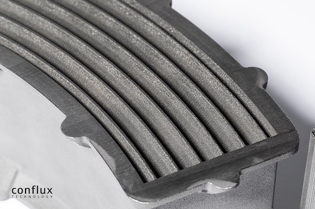
    Conflux Technology Monel K test part and close up.

    The 3D Printing Process

    To bring this project to fruition, Conflux and RFA will focus on the materials qualification and testing of Monel 500K, a high-performance alloy known for its excellent mechanical properties and resistance to extreme temperatures. The production platform for the heat exchangers will be the EOS M300-4, a state-of-the-art metal 3D printing system. The goal is to develop, build, and functional test the Gas Duct Heat Exchanger in 2023.

    A Pioneering Partnership

    This collaboration between Conflux and RFA is a testament to the transformative potential of additive manufacturing in the aerospace industry. By combining their respective expertise in 3D printing and rocket engineering, they are poised to create advanced heat exchangers that could redefine the performance and efficiency of future space missions.

    As the space race heats up, this groundbreaking partnership between Conflux Technology and Rocket Factory Augsburg stands as an exciting development for both the Australian and global space industries. The integration of advanced 3D printed heat exchangers into orbital rockets promises not only to improve performance but also to propel us closer to the ambitious goals of lunar and Martian exploration.

    via Conflux Technology

  • AI-Assisted OpenSCAD Design for 3D Printing: Workflow, Prompts and Validation

    AI-Assisted OpenSCAD Design for 3D Printing: Workflow, Prompts and Validation

    AI coding assistants can help write, explain and refactor OpenSCAD scripts. This makes parametric 3D modeling more accessible, but the generated code is only a draft. The designer remains responsible for geometry, dimensions, tolerances, manufacturability and safe use of the printed part.

    Treat an AI model as a coding assistant, not as the design authority. Render, measure, inspect, slice and physically validate every generated model.

    Why OpenSCAD works well with AI

    OpenSCAD is a script-based solid-modeling tool. Geometry is created through primitives, transformations, Boolean operations, functions, modules and parameters. Because the design is expressed as text, a language model can assist with:

    • Drafting simple parametric models
    • Explaining existing code
    • Converting repeated geometry into modules and loops
    • Adding configurable dimensions and Customizer variables
    • Finding syntax mistakes and duplicated logic
    • Creating design variants and test coupons
    • Writing command-line batch-generation scripts
    • Adding comments, assertions and basic tests

    OpenSCAD is especially effective for dimension-driven brackets, spacers, enclosures, adapters, fixtures, patterns and model families. Organic surfaces, complex assemblies and history-based mechanical design may be better handled in other CAD systems.

    The safe AI-assisted workflow

    StageAI can help withHuman or deterministic validation
    1. RequirementsTurn notes into a structured parameter listConfirm function, loads, interfaces and constraints
    2. Code draftGenerate modules, functions and geometry logicReview every line and assumption
    3. RenderInterpret errors and suggest fixesCompile and render in OpenSCAD
    4. Geometry checkSuggest tests and edge casesMeasure dimensions, wall thickness and clearances
    5. ExportPrepare batch commands or naming rulesExport a valid mesh and inspect it
    6. SlicingExplain settings and tradeoffsUse a validated printer/material profile
    7. PrototypeCreate a test planPrint, fit, load-test and document results
    8. ReleaseGenerate comments and change notesVersion-control the approved script and output

    1. Write requirements before asking for code

    A vague prompt such as “make a strong bracket” forces the AI to invent critical design decisions. Begin with a short specification:

    • Overall envelope and units
    • Interface dimensions and hole locations
    • Minimum wall thickness
    • Required clearance, interference or tolerance
    • Printer process, nozzle and material
    • Preferred build orientation
    • Expected loads and environment
    • Features that must remain editable
    • Forbidden assumptions
    • Required output and validation checks

    For safety-relevant parts, OpenSCAD code and a printed prototype do not replace engineering analysis, material data or qualification.

    2. Use named parameters and assertions

    The following example creates a hollow cylindrical spacer. It improves on the older article by defining units, exposing parameters, checking impossible inputs and avoiding coincident end faces:

    // Parametric hollow spacer — dimensions in millimeters
    outer_diameter = 30;
    wall_thickness = 5;
    height = 50;
    facet_count = 120;
    epsilon = 0.05;
    
    inner_diameter = outer_diameter - 2 * wall_thickness;
    
    assert(outer_diameter > 0, "Outer diameter must be positive");
    assert(height > 0, "Height must be positive");
    assert(wall_thickness > 0, "Wall thickness must be positive");
    assert(inner_diameter > 0, "Wall thickness is too large");
    
    module hollow_spacer(od, id, h) {
        difference() {
            cylinder(h = h, d = od, $fn = facet_count);
            translate([0, 0, -epsilon])
                cylinder(h = h + 2 * epsilon, d = id, $fn = facet_count);
        }
    }
    
    hollow_spacer(outer_diameter, inner_diameter, height);

    The code can render correctly and still be unsuitable for the application. The designer must verify whether a 5 mm wall, 30 mm diameter and selected material can carry the actual load.

    3. Ask the AI to expose assumptions

    A stronger prompt asks for a design plan before code:

    Create a parametric OpenSCAD model for a hollow spacer. Units are millimeters. Required parameters: outer diameter, wall thickness, height and facet count. Before writing code, list your geometric assumptions, invalid parameter combinations and printability concerns. Then generate readable code with named variables, modules, comments and assert statements. Do not claim structural suitability.

    For modification work:

    Review this OpenSCAD script without changing it. Identify syntax errors, non-manifold risks, coincident Boolean surfaces, unit ambiguity, hidden constants, parameter edge cases and features likely to print poorly. Return findings first, then provide the smallest corrected version.

    4. Validate the script in OpenSCAD

    1. Compile and preview. Resolve syntax and undefined-variable errors.
    2. Perform a full render. Preview can hide Boolean or mesh problems that appear during CGAL rendering.
    3. Read warnings. Do not ignore empty geometry, invalid polygons or non-manifold conditions.
    4. Measure the model. Confirm overall dimensions, center positions, wall thicknesses and clearances.
    5. Test parameter limits. Try minimum, maximum and invalid values.
    6. Inspect section views. Check hidden intersections, trapped volumes and internal features.
    7. Export a mesh. Use STL or 3MF as supported by the workflow.
    8. Inspect the exported file. Confirm scale, orientation, watertightness and triangle quality.

    5. Validate manufacturability in the slicer

    OpenSCAD creates geometry; it does not prove printability. A slicer and physical process review should check:

    • Minimum printable walls and gaps
    • Hole compensation and thread strategy
    • Overhangs, bridging and supports
    • Part orientation and anisotropic strength
    • Warping, shrinkage and bed adhesion
    • Nozzle width, layer height and feature resolution
    • Material, temperature and environmental limits
    • Support removal and post-processing access
    • Print time, material use and failure consequence

    Use the complete sliced preview. A model that looks correct in CAD can contain unprintable thin regions, unsupported islands or internal spaces that trap resin or powder.

    6. Calibrate fits instead of trusting nominal dimensions

    A requested 10 mm hole will not necessarily print as 10 mm. Dimensional outcome depends on process, material, orientation, exposure or extrusion, shrinkage and machine calibration. Build a small coupon containing several offsets and record the result.

    FeatureRecommended validation
    Sliding fitPrint a clearance ladder around the target dimension
    Press fitTest material and orientation-specific interference values
    Fastener holeDecide whether to print undersize and drill/ream
    ThreadCompare printed, tapped and insert-based options
    Snap featureCycle-test strain, creep and environmental exposure
    Seal surfaceMachine or finish when roughness and flatness are critical

    7. Use automated tests for model families

    Parametric designs become much safer when edge cases are tested automatically. A simple release workflow can:

    • Render several approved parameter combinations from the command line
    • Fail when an assertion is triggered
    • Confirm expected bounding-box dimensions
    • Check that exported meshes are watertight
    • Compare file or mesh changes against a baseline
    • Generate uniquely named variants with parameter metadata
    • Retain the OpenSCAD version and library dependencies

    AI can draft the test script, but deterministic tools should decide whether the build passes.

    Common AI-generated OpenSCAD problems

    • Correct syntax but wrong engineering interpretation
    • Mixed millimeter and inch assumptions
    • Negative or impossible dimensions
    • Coincident surfaces that create unstable Boolean results
    • Extremely high $fn values that make rendering unnecessarily slow
    • Extremely low facet counts that alter functional geometry
    • Hidden hard-coded values instead of parameters
    • Open or self-intersecting imported polygons
    • Unprintable overhangs, gaps or wall thicknesses
    • Unsupported claims about strength, heat resistance or safety
    • Use of libraries, syntax or functions that do not exist
    • Code that produces the intended appearance but incorrect interfaces

    Where AI plus OpenSCAD is strongest

    • Adjustable spacers, washers, bushings and adapters
    • Enclosures with configurable dimensions
    • Drill, assembly and inspection fixtures
    • Storage inserts and organizers
    • Calibration coupons and test matrices
    • Repeated patterns and arrays
    • Simple gears, knobs and mechanical utilities with verified geometry
    • Mass-customized variants generated from controlled parameters

    Where another CAD approach may be better

    • Complex assemblies with mating and motion relationships
    • Freeform class-A or ergonomic surfaces
    • Detailed drawings and model-based definition
    • Finite-element-driven structural design requiring certified workflows
    • Complex fillets, blends and editable feature history
    • Regulated production requiring enterprise PLM and configuration control

    Version control and intellectual property

    OpenSCAD files are text and work well with Git or other version-control systems. Keep the source script, parameter set, exported mesh, slicer profile and validation record linked. Review the licenses of imported models and libraries. Do not paste confidential product definitions into an AI service unless organizational policy and data controls permit it.

    Conclusion

    AI and OpenSCAD form a useful rapid-design pair because natural-language requirements can be translated into readable parametric code. The productivity benefit comes from faster drafting and iteration—not from eliminating engineering judgment. A dependable workflow exposes assumptions, adds assertions, renders and measures the geometry, validates manufacturability in the slicer and verifies the physical part.

    Related Addithive resources: AI and G-code Safety · Industrial AM Software Guide

    References and further reading

  • Insource or Outsource Additive Manufacturing? A Make-or-Buy Framework

    Insource or Outsource Additive Manufacturing? A Make-or-Buy Framework

    The decision to insource or outsource additive manufacturing is not simply a comparison between machine price and supplier quotation. It is a capability decision involving application pipeline, utilization, intellectual property, process ownership, qualification, post-processing, inspection and long-term supply risk.

    Buy a machine when owning the manufacturing capability creates durable strategic value. Buy parts when external capability delivers the required result with lower total risk.

    Three operating models

    ModelWhat remains internalBest fit
    OutsourceRequirements, design authority, supplier management and acceptanceEarly adoption, variable demand, specialized processes or limited internal expertise
    HybridApplication engineering, prototyping or selected builds; external production or post-processingOrganizations building knowledge while managing capital and qualification risk
    InsourceEquipment, operators, process control, production data and often post-processingStrategic IP, stable workload, rapid iteration, controlled qualification or supply-chain need

    Many successful programs move through these models over time. Outsourcing can be the fastest way to validate applications. A hybrid model can build internal design and process knowledge. Full insourcing becomes attractive only when the application portfolio, organization and downstream infrastructure are ready.

    The first question: what capability are you buying?

    An AM machine does not create an industrial capability by itself. A complete capability may require:

    • Application and DfAM engineering
    • Build preparation and process engineering
    • Feedstock storage, handling and traceability
    • Qualified equipment, software and parameters
    • Environmental, health and safety controls
    • Heat treatment, HIP, debinding or sintering
    • Support removal, machining and surface finishing
    • Cleaning, metrology, NDT and material testing
    • Quality systems, data retention and change control
    • Maintenance, service and spare-parts support

    If most of these remain external, the organization may be insourcing a printer while still outsourcing the production system.

    When insourcing is strategically attractive

    Rapid design–build–test loops

    Internal equipment can compress iteration cycles when engineers, operators and test teams work closely. This is valuable for R&D, tooling, repair development and products whose geometry changes frequently.

    Sensitive intellectual property

    Insourcing can reduce exposure of geometry, parameters and performance data. It does not remove cybersecurity risk; internal access, file transfer and machine networks still need control.

    Stable and repeatable demand

    A credible internal application pipeline improves equipment utilization and supports operator proficiency. The pipeline should be based on production-ready candidates rather than a long list of parts that are merely printable.

    Qualification ownership

    Some organizations need direct control of parameters, machine condition, material genealogy and production records. This can justify insourcing when the qualification burden is strategic and long-lived.

    Supply-chain resilience

    Internal AM may reduce lead time for tooling, spares, repair or obsolete components. The benefit is real only if feedstock, post-processing, inspection and approved data remain available during the disruption being mitigated.

    When outsourcing is stronger

    Demand is uncertain or intermittent

    Service providers can aggregate demand across customers and technologies. This avoids carrying expensive underutilized equipment and specialist labor.

    The process is highly specialized

    Large-format DED, electron-beam PBF, reactive-metal production, high-resolution CT, HIP, advanced surface finishing and specialized furnace routes may be difficult to justify internally.

    Speed to first part matters

    An experienced supplier with qualified equipment and downstream operations can deliver useful evidence faster than a new internal team can install, stabilize and validate a production line.

    Technology flexibility matters

    Outsourcing allows an organization to compare LPBF, binder jetting, polymer PBF, DED and other routes without committing capital to one platform. This is valuable during application discovery.

    External qualification already exists

    A supplier may already hold customer approvals, material data, special-process accreditations and production experience that would take years to replicate.

    The make-or-buy decision matrix

    Decision factorFavors insourcingFavors outsourcing
    Application demandStable, recurring and visibleVariable, early-stage or project-based
    Strategic differentiationProcess knowledge or iteration creates competitive advantagePart is non-core or commercially available
    IP sensitivityGeometry and parameters are highly sensitiveControlled supplier exchange is acceptable
    Technology breadthOne process family covers most needsApplications require several technologies or materials
    QualificationLong-term program justifies internal qualificationSupplier holds relevant approvals and evidence
    Lead timeFrequent urgent demand benefits from local controlQualified supplier can deliver faster than capability build-up
    Capital and utilizationHigh utilization and funded infrastructureLow or uncertain utilization
    TalentExperienced multidisciplinary team can be retainedCritical expertise is unavailable internally
    Post-processingRequired downstream operations are controlled internallySupplier provides an integrated finished-part route
    Supply riskExternal capacity or geopolitical exposure is unacceptableMultiple qualified suppliers provide resilience

    Calculate total cost of ownership

    The internal cost model should include more than equipment depreciation:

    • Facility preparation, utilities, inert gas and ventilation
    • Powder-safe or material-specific handling systems
    • Software licenses and computing infrastructure
    • Machine acceptance, calibration and maintenance
    • Engineering, operator and quality labor
    • Training and qualification
    • Feedstock inventory, testing and obsolescence
    • Build failures, rework and development builds
    • Heat treatment, machining, finishing and inspection
    • Data systems, cybersecurity and record retention
    • Downtime, spare parts and service contracts
    • Cost of underutilized capacity

    The supplier quotation should also be normalized. Determine whether it includes design support, material, post-processing, inspection, documentation, shipping, non-recurring engineering and qualification. Compare cost per accepted finished part, not print-hour rate.

    Utilization is necessary but not sufficient

    High machine utilization can still destroy value if the portfolio consists of low-value parts or development work that never transitions to production. Track:

    • Productive versus experimental build hours
    • First-pass yield and accepted-part output
    • Post-processing queue and total lead time
    • Engineering hours per released part
    • Value created through performance, tooling avoidance or lead-time reduction
    • Percentage of applications reaching recurring production

    Qualification ownership must be explicit

    Outsourcing does not transfer engineering accountability automatically. The customer and supplier should define who owns:

    • Part design and DfAM decisions
    • Material and process specifications
    • Parameter approval and change control
    • Machine equivalency and site transfer
    • Heat-treatment and post-processing approval
    • Inspection technique and acceptance criteria
    • Nonconformance disposition
    • Data retention and audit access

    ISO/ASTM 52901 provides a useful basis for defining the information exchanged between the purchaser and AM part provider, including part definition, feedstock, final characteristics, inspection and acceptance.

    How to evaluate an AM supplier

    1. Relevant experience: Has the supplier produced comparable geometry, alloy and criticality?
    2. Process control: How are parameters, software, machine state and material lots controlled?
    3. Downstream integration: Which post-processing and inspection steps are internal or subcontracted?
    4. Quality evidence: What qualifications, accreditations, material data and historical yield exist?
    5. Change management: What changes require customer notification or approval?
    6. Capacity: What is the actual bottleneck at target volume?
    7. Data and IP: Who owns build files, supports, parameters, monitoring data and improvement knowledge?
    8. Business continuity: Are service, spare parts, secondary machines and backup sites available?
    9. Transparency: Will the supplier share nonconformance, yield and root-cause information?
    10. Exit plan: Can production be transferred if the supplier or platform becomes unavailable?

    The hybrid model

    A hybrid model often provides the best learning-to-risk ratio. Common configurations include:

    • Internal polymer printing and DfAM; external metal production
    • Internal prototype metal machine; qualified production at a supplier
    • Internal LPBF; external HIP, machining or CT
    • Internal application engineering and inspection; external build execution
    • Dual sourcing between an internal line and an external qualified partner

    The interfaces must be explicit. A fragmented hybrid route can create more logistics and configuration risk than either full insourcing or an integrated supplier.

    A staged decision process

    1. Build a process-neutral application pipeline.
    2. Outsource representative parts to establish real cost, quality and lead time.
    3. Develop internal DfAM, sourcing and acceptance capability.
    4. Identify the recurring bottleneck: supplier capacity, iteration speed, IP, cost or qualification.
    5. Model internal utilization and complete infrastructure requirements.
    6. Compare outsource, hybrid and insource scenarios over the program life.
    7. Run a pilot capability with measurable transition criteria.
    8. Scale only after accepted-part economics and organizational readiness are demonstrated.

    Red flags before buying a machine

    • The business case depends on a single unqualified part.
    • Post-processing and inspection are described as future problems.
    • Utilization assumptions use maximum build hours rather than accepted-part demand.
    • No one owns material, parameter and configuration control.
    • The team lacks dedicated process and quality resources.
    • The selected machine is justified by demonstrations rather than requirements.
    • The cost model excludes development failures, downtime and labor.
    • There is no plan for software, machine or supplier obsolescence.

    Conclusion

    Insourcing is justified when AM capability is strategically important, the application pipeline is credible and the organization can control the complete production route. Outsourcing is stronger when demand is uncertain, technology breadth matters or qualified external capability already exists. A staged hybrid approach is often the safest path from experimentation to industrial production.

    Related Addithive resources: Industrial AM Workflow · Metal AM Supply Chain Map

    References and further reading

  • Formlabs Launches TPU 90A Powder, the First Elastomer Material for Fuse Series 3D Printers

    Formlabs Launches TPU 90A Powder, the First Elastomer Material for Fuse Series 3D Printers

    Attention all 3D printing enthusiasts! The news is out and it’s hot off the press. Formlabs, the leading 3D printing company, has just announced the release of their newest material for Fuse Series printers – TPU 90A Powder! This tough elastomer powder is a game-changer for a variety of industries, including healthcare, consumer goods, manufacturing, and engineering.

    This high-performance material is no joke, folks. Its strength and flexibility enable the production of fully functional parts in-house, giving engineers and manufacturers complete design freedom and a seamless workflow on the Fuse Series SLS 3D printing ecosystem. That’s right, you read it correctly. Fully functional parts created in-house. Who wouldn’t want that kind of control over their supply chain?

    But wait, there’s more. TPU 90A Powder is not only ideal for manufacturing aids and end-use parts, but it’s also perfect for creating soft touch components such as grippers, padding, and cushions. The possibilities are endless with this material.

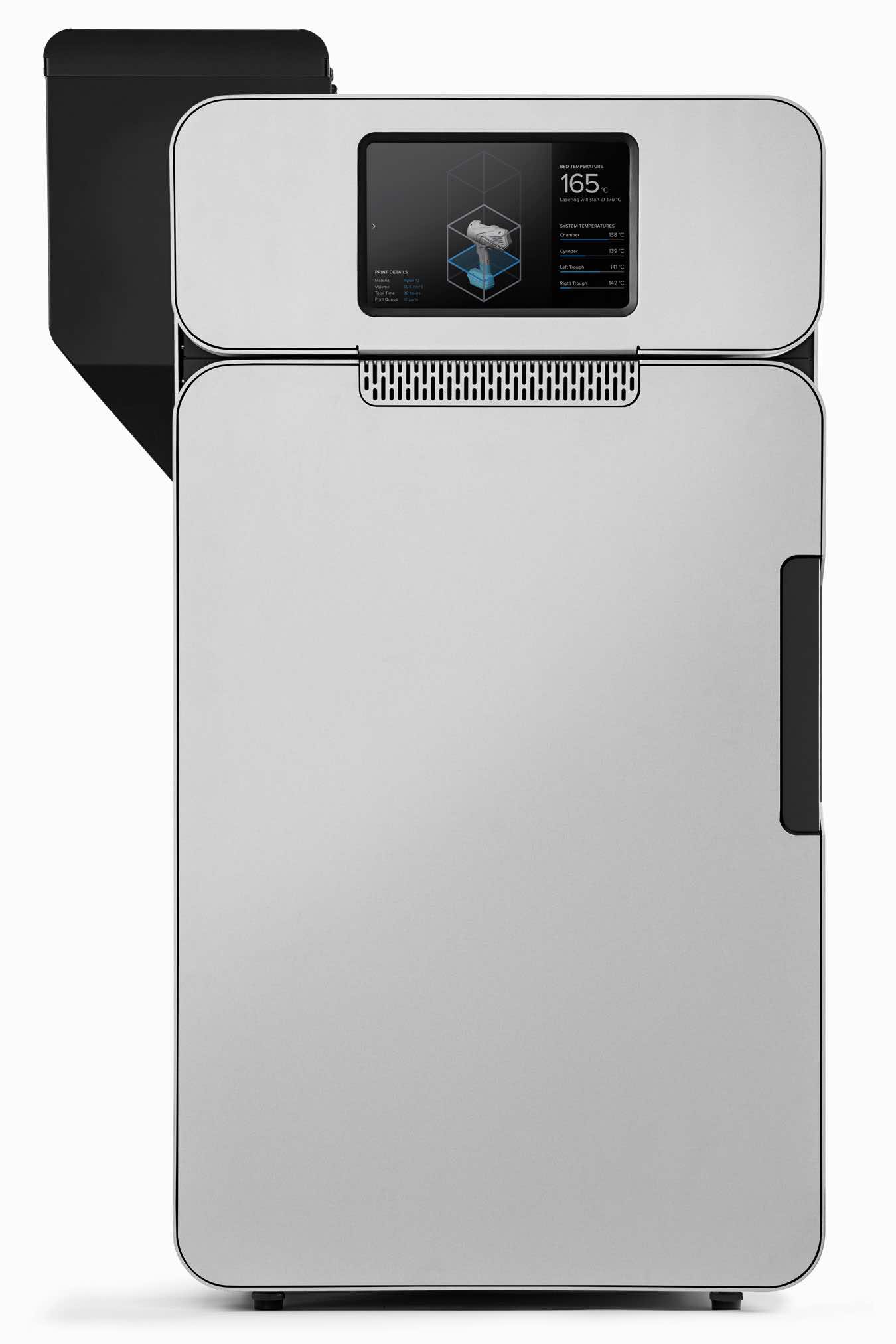
    Formlabs Fuse System

    What’s more, TPU 90A Powder is validated for skin contact, making it a prime candidate for medical applications. Prosthetics, orthotics, and other patient-specific devices requiring custom designs are no match for this material. Its softness and flexibility ensure optimal comfort and performance, ultimately improving outcomes in patient care and streamlining the medical device manufacturing process.

    Formlabs’ Chief Product Officer, Dávid Lakatos, couldn’t be more excited about the release of TPU 90A Powder. “With the release of TPU 90A Powder, we’re proud to offer a material that expands the possibilities for 3D printing across many industries, enabling users to create flexible, skin-safe parts tailored to their specific applications,” Lakatos said.

    And if you’re worried about the cost, fear not. TPU 90A Powder boasts a low cost per part for low volume production of 3D printed, flexible parts. Plus, with a refresh rate of 20%, there’s lower waste and higher efficiency, making it a smart investment for any business.

    But wait, there’s more! Formlabs’ TPU 90A Powder is part of their growing library of SLS materials, enabling their customers to create parts with a range of properties including stiffness, softness, ductility, and thermal stability. It’s no wonder Formlabs is the leading 3D printing company in the game.

    Formlabs TPU 90A SLS Powder Parts via Formlabs

    And the best part? You can get your hands on this innovative material right now. That’s right, TPU 90A Powder is available for order, and Formlabs will be showcasing it at the Formlabs booth at AMUG 2023 (booth D14).

    So, what are you waiting for? Get your creative juices flowing and let your imagination run wild with the possibilities of TPU 90A Powder. With its strength, flexibility, and skin-safe properties, the sky’s the limit when it comes to what you can create. Let’s get printing!

  • Revolutionizing Spaceflight: How Additive Manufacturing is Disrupting the Industry

    Revolutionizing Spaceflight: How Additive Manufacturing is Disrupting the Industry

    Metal Additive Manufacturing (AM) is a process that has been gaining popularity in recent years due to its ability to create complex parts with intricate geometries that are not easily manufactured by traditional methods. In the rocket engine industry, this technology has the potential to revolutionize the manufacturing process by reducing lead times, decreasing costs, and improving engine performance.

    One of the most significant advantages of metal AM is the ability to create designs that were previously impossible. For example, complex internal cooling channels can be printed in a single part, without the need for assembly. This reduces lead time, simplifies assembly, and can improve engine performance. In addition, metal AM can enable the use of materials that were previously difficult to process or not possible. For example, the use of refractory metals or alloys that are oxidation-resistant can now be explored. This can result in improved engine performance and durability.

    However, it is important to note that metal AM is not a solve-all solution for rocket engine manufacturing. Various AM processes have unique advantages and disadvantages that need to be considered when selecting the appropriate process for a specific application. It is important to consider factors such as the required alloy, overall part size, feature resolution, internal complexities, and programmatic requirements. The end-use environment and qualification/certification path should also be considered.

    Photo by Pixabay on Pexels.com

    Material properties are highly dependent on the type of process, starting feedstock chemistry, process parameters, and heat treatment processes used post-build. Heat treatments should be developed based on the requirements and environment of the end component use. The process requires a complete understanding of the design process, build-process, feedstock, and post-processing to fully take advantage of AM. It takes practice to master the process. Standards and certification of the AM processes are still evolving.

    The ongoing development of AM processes, understanding of microstructure and properties, and advancements in testing and post-processing techniques are critical for the continued improvement of metal AM. Combining various AM processes for multi-alloy solutions or additional design options is also being explored. Additionally, the advancement of commercial supply chains for unique alloys and new alloy development is ongoing.

    A material database of metal AM properties can allow for conceptual design and design complexity using lattices and thin-wall structures. Standards and certification of metal AM for human spaceflight are also evolving. As metal AM continues to evolve, it is important to consider the impact on supply chains and manufacturing processes. For example, the use of metal AM can lead to reduced lead times and reduced tooling costs. However, it can also lead to the need for new post-processing techniques and heat treatments. It is important to consider these factors when evaluating the use of metal AM for rocket engine manufacturing.

    The ongoing development of AM processes has led to various processes that have matured for rocket propulsion applications, each with unique advantages and disadvantages. These processes include Laser Powder Bed Fusion (L-PBF), Directed Energy Deposition (DED), Ultrasonic Additive Manufacturing (UAM), and Cold spray, among others. While AM is not a solve-all solution, it should be considered alongside other manufacturing technologies when it makes sense.

    Photo by Javier Mendoza on Pexels.com

    Furthermore, AM has the potential to provide significant advantages for lead time and cost over traditional manufacturing for rocket engines. The inherent complexity of liquid rocket engines can be addressed through new designs, part consolidation, and performance opportunities. Materials that were previously difficult to process using traditional techniques, long-lead, or not previously possible can now be accessed using metal additive manufacturing.

    Material properties are highly dependent on the type of process, starting feedstock chemistry, process parameters, and heat treatment processes used post-build. Heat treatments should be developed based on the requirements and environment of the end component use. The process requires a complete understanding of the design process, build-process, feedstock, and post-processing to fully take advantage of AM. It takes practice to master the process. Standards and certification of the AM processes are still evolving.

    AM development at NASA

    The ongoing development of AM processes, understanding of microstructure and properties, and advancements in testing and post-processing techniques are critical for the continued improvement of metal AM. Combining various AM processes for multi-alloy solutions or additional design options is also being explored. Additionally, the advancement of commercial supply chains for unique alloys and new alloy development is ongoing.

    A material database of metal AM properties can allow for conceptual design and design complexity using lattices and thin-wall structures. Standards and certification of metal AM for human spaceflight are also evolving. As metal AM continues to evolve, it is important to consider the impact on supply chains and manufacturing processes. For example, the use of metal AM can lead to reduced lead times and reduced tooling costs. However, it can also lead to the need for new post-processing techniques and heat treatments. It is important to consider these factors when evaluating the use of metal AM for rocket engine manufacturing.

    Another area of ongoing development is the certification of metal AM for human spaceflight. As metal AM is explored for use in critical applications such as rocket engines, it is important to ensure that the processes and materials meet the necessary safety and performance requirements. Standards and certification of metal AM for human spaceflight are evolving, and ongoing development in this area will enable the technology to be used in critical applications such as rocket engines.

    In conclusion, metal AM has the potential to revolutionize the manufacturing of rocket engines through reduced lead times, decreased costs, and the ability to create designs that were previously impossible. However, it is important to have a complete understanding of the process and consider various factors when selecting the appropriate AM process for a specific application. With ongoing development and advancements, the possibilities of metal AM are limitless.