Tag: metal 3D printing

  • Additive Manufacturing is No Longer the Future

    Additive Manufacturing is No Longer the Future

    It’s the Engine of Industrial Transformation

    By mid-2025, additive manufacturing (AM) has broken out of the prototyping corner and taken center stage as a pillar of Industry 4.0. With a global market value projected to soar from $20.37 billion in 2023 to $88.28 billion by 2030, at a staggering 23.3% CAGR, AM is no longer an emerging technology—it is a strategic enabler of design freedom, supply chain resilience, and sustainable production.

    What’s driving this explosive trajectory? A potent mix of next-generation hardware, novel material breakthroughs, automation-first workflows, and globally coordinated regulatory frameworks. And yet, for all its promise, AM’s future hinges on our ability to scale precision, ensure repeatability, and harmonize standards. This article unpacks the current state and near-future outlook for additive manufacturing through three pivotal lenses: technological innovationregulatory evolution, and regional momentum.


    From Prototype to Production – How Next-Gen Additive Technologies Are Breaking Barriers

    “From five-micron tolerance to decentralized, high-volume output, AM is reinventing how we think about manufacturing itself.”

    By 2025, the range and maturity of AM technologies have expanded dramatically. Innovations now span nearly every corner of the additive toolbox, each solving a specific pain point in the production chain:

    🔧 Precision and Performance

    High-resolution powder bed fusion systems like Aixway3D’s Precision-100 deliver tolerances as tight as 2–5 microns, enabling aerospace-grade parts with minimal post-processing. Meanwhile, selective laser sintering (SLS) solutions from 3DPS now hit 1 mm wall thickness with 0.2 mm precision—capabilities critical for functional parts in aerospace and healthcare.

    Additive manufacturing machine with a control panel, a screen, and various components designed for precision 3D printing.
    https://aixway3d.de

    🤖 Automation and Scaling

    Automation has moved from vision to implementation. AM-Flow’s robotic workflows and Printinue’s continuous production loops allow fully digitized, lights-out manufacturing. These systems aren’t just cost savers—they’re the scaffolding for decentralized, on-demand production hubs.

    🧪 Material Science at the Forefront

    Sustainability and performance are converging. f3nice is commercializing recycled metal powders, while Foundation Alloy focuses on high-performance, application-specific metals. In the polymer world, RAYSHAPE’s DLP machines and NematX’s liquid crystal polymers (LCP) are redefining precision and durability.

    🧬 Biological Integration

    Bioprinting is transitioning from lab experiment to clinical pilot. Brinter’s modular bioprinters are enabling scaffold fabrication for tissue engineering, while medical-grade resins are entering the DLP mainstream thanks to Boston Micro Fabrication.

    🏭 High-Volume Breakthroughs

    Q.big 3D’s QUEEN 1 introduces Volumetric Filament Grid Fusion (VFGF), enabling affordable large-part production. Pair this with Phasio’s decentralized manufacturing software, and the result is an elastic production model, ready for reshoring supply chains.

    A modern 3D printer, labeled 'QUEEN 1' by Q.big 3D, designed for high-volume additive manufacturing, featuring a sleek black and white exterior.
    https://www.qbig3d.de/

    Yet, for all the progress, challenges persist: throughput in metal AM remains relatively low; material costs are still high for certain alloys and biocompatible resins; and post-processing—though improving—is often the bottleneck in full-stack workflows.


    The Rules Are Changing – Regulation, Standardization, and Safety in a Maturing Ecosystem

    “AM’s growth is as much about digital lasers as it is about legal lines.”

    As additive manufacturing moves into regulated industries—healthcare, aerospace, defense—the rulebook is expanding fast. The real story of 2025 isn’t just what we can print, but what we’re allowed to.

    the word compliance written in scrabble letters

    🧭 Healthcare: Navigating FDA Waters

    The U.S. FDA’s framework for additive medical devices demands rigorous testing on porosity, mechanical integrity, and traceability. While this ensures patient safety, smaller companies often face steep regulatory and cost barriers. Quality assurance software, in-situ monitoring, and ISO-aligned certification programs are becoming baseline requirements.

    ✈ Aerospace & Safety Protocols

    The EN ISO/ASTM 52938-1 standard in Europe now governs laser beam and powder machine safety, with ISO/ASTM 52931 setting the groundwork for metallic material properties. These standards are essential—but introduce a lag between tech innovation and regulatory acceptance. The result? Slower integration of novel materials in high-stakes use cases.

    🧠 Intellectual Property in a Digital World

    2025 IP landscape is shifting. With digital inventories and mass customization, we’re entering an era of design ownership complexity. Licensing platforms and blockchain verification may offer the next frontier in securing AM intellectual property.

    🔒 Sector-Specific Limits: Formula 1 & Defense

    Regulation isn’t always enabling. Formula 1’s 2026 technical guidelines now limit AM for critical components like heat exchangers—highlighting how even proven technologies can be gated when safety margins are razor-thin.

    So what’s the path forward? Ongoing standardization and government-supported certification labs—like those seen in India and the U.S.—are helping harmonize global frameworks. But until regulations match innovation speed, AM will need to navigate cautiously through fragmented compliance landscapes.


    Around the World in 3D – Regional Powerhouses and National Strategies

    “In the global AM race, innovation is local—but ambition is universal.”

    The geographic spread of additive manufacturing tells a compelling story: while the technology is global, its development is deeply regional. Each powerhouse has distinct goals, advantages, and policy frameworks.

    close up of globe

    🇺🇸 North America – Defense, Healthcare, and Private Capital

    With >34% global market share, the U.S. leads in AM R&D and deployment. Initiatives like America Makes and NIST’s metrology efforts drive certification and workforce development. The sector thrives on defense and aerospace demand, bolstered by deep venture capital pools (over $600M in VC funding in 2018 alone).

    🇪🇺 Europe – Innovation Through Standardization

    Home to EOS, Materialise, and Voxeljet, Europe’s AM leadership rests on strong public-private R&D. EU initiatives fund sustainability-focused programs, while standardization bodies build the backbone for cross-border interoperability.

    🇮🇳 India – AM as a Strategic Leapfrog

    India’s 2022 National Strategy set bold goals: 100 startups, 100,000 trained workers, and 50 certified AM products by 2025. With Atal Tinkering Labs and seven state-funded AM centers, India is fast-tracking homegrown innovation. Healthcare and tooling are immediate beneficiaries.

    🇨🇳 China – Industrialization and Scale

    Though detailed 2025 stats were lacking, policy momentum points to AM’s central role in China’s manufacturing modernization. With strengths in automotive and consumer electronics, China’s scale advantage and national industrial policies make it a formidable player.

    Regional insights also reveal who’s betting big on decentralized manufacturing. For instance, India’s state-level partnerships and U.S. startups using Phasio’s cloud-driven tools point toward a future of “digital-first factories”—where agility, not just output, defines competitiveness.


    The Next Five Years Will Redefine What We Call a Factory

    Additive manufacturing in 2025 isn’t a novelty—it’s a necessity. As supply chains de-risk, as sustainability moves from CSR to ROI, and as engineers demand more from geometry and performance, AM answers the call.

    But the real transformation lies ahead. From 2025 to 2030, we’ll likely see:

    • Cost parity with traditional methods through high-throughput and automated workflows
    • Explosive material diversity, including bioresorbable implants and aerospace-grade recycled alloys
    • Mainstream adoption of hybrid AM-CNC lines for mass customization
    • Wider use of digital inventories, fundamentally changing spare parts and MRO economics


    If you’re leading innovation in engineering or manufacturing, now is the time to ask: Is your product portfolio designed for AM? Are your teams trained in DfAM principles? Are your suppliers AM-capable?

    The next industrial leap won’t be won by those who wait for standards to stabilize or costs to drop—it will be led by those who experiment, partner, and evolve with the technology.

    The additive future is not just being built. It’s being printed—one micron at a time.


    Technical Terms:

    • AM – Additive Manufacturing
    • PBF – Powder Bed Fusion
    • SLS – Selective Laser Sintering
    • DLP – Digital Light Processing
    • LCP – Liquid Crystal Polymer
    • VFGF – Volumetric Filament Grid Fusion
    • FDM – Fused Deposition Modeling
    • WAAM – Wire Arc Additive Manufacturing
    • DED – Direct Energy Deposition

    Design and Process Frameworks:

    • DfAM – Design for Additive Manufacturing
    • TRL – Technology Readiness Level
    • CAD – Computer-Aided Design

    Standards and Regulatory Bodies:

    • EN ISO/ASTM 52938-1 – European/International Standard for Safety in Laser-Based Additive Manufacturing Machines
    • ISO/ASTM 52931 – Standard for Metallic Materials in Additive Manufacturing
    • FDA – Food and Drug Administration
    • NIST – National Institute of Standards and Technology

    Organizations and Initiatives:

    • R\&D – Research and Development
    • VC – Venture Capital
    • IP – Intellectual Property

    📚 Works Cited

    America Makes. Public-Private Partnership for Additive Manufacturing. 2025.

    AMFG. Additive Manufacturing Around the World: North America and Europe. Additive Manufacturing Global, 2025.

    Engineering.com. Additive Manufacturing Progress Update – April 2025. 2025.

    Grand View Research. Additive Manufacturing Market Size Report, 2030. 2025.

    India Brand Equity Foundation (IBEF). National Strategy on Additive Manufacturing. 2022.

    KAN – Kommission Arbeitsschutz und Normung. Standardization in Additive Manufacturing. 2025.

    Massivit. 3D Printing Trends: Additive Manufacturing 2025. 2025.

    MotoPaddock. Additive Medical Implants 2025: Rapid Growth & Disruptive Innovation. 2025.

    National Institute of Standards and Technology (NIST). Additive Manufacturing Initiatives. 2025.

    ScienceDirect. Economic and Regulatory Perspectives on Additive Manufacturing. 2025.

    Silicon UK Tech News. The State of Additive Manufacturing 2025. 2025.

    StartUs Insights. Top 10 Additive Manufacturing Trends in 2025. 2025.

    VoxelMatters. Exploring Additive Manufacturing in the 2026 Formula 1 Technical Regulations. 2025.

  • NUBURU Introduces Next-Generation 1 Kilowatt Blue Laser Technology

    NUBURU Introduces Next-Generation 1 Kilowatt Blue Laser Technology

    NUBURU, a renowned leader in high-power and high-brightness industrial blue laser technology, has recently announced the introduction of its latest innovation, the NUBURU BL-1000-F. This next-generation 1-kilowatt blue laser is set to make a significant impact on several large and rapidly growing industries, including EV battery production, metal 3D printing, and consumer electronics. With its increased power and enhanced capabilities, the BL-1000-F is poised to revolutionize manufacturing processes and empower businesses to achieve new levels of efficiency and precision.

    Harnessing the Power of Blue Light: The NUBURU BL-1000-F stands out due to its ability to leverage the inherent high absorption of metals to blue light. This unique characteristic allows for superior performance in welding and processing applications. By utilizing the higher power delivered by the BL-1000-F, manufacturers can achieve higher quality laser beams, enabling efficient welding and processing of highly reflective metals that pose challenges for traditional infrared lasers. This breakthrough technology opens up new possibilities for EV battery production and metal additive 3D printing, where precision and process stability are crucial.

    Nuburu Blue Light Laser
    Blue Laser Area Printing – Nuburu

    Advancing Manufacturing Capabilities: The introduction of the BL-1000-F addresses the needs expressed by customers, who have eagerly awaited a solution that combines speed and weld quality. This powerful laser system enables higher speed and micron-level precision, paving the way for faster, more reliable, and repeatable high-quality welds. With the ability to meet these critical requirements, the BL-1000-F empowers manufacturers to enhance their capabilities across various industries.

    Enhanced Welding and Additive Manufacturing: One of the primary applications of the BL-1000-F lies in EV battery welding. As electric vehicles continue to gain momentum, the demand for efficient and reliable battery production methods increases. The BL-1000-F’s higher power and improved weld quality enable manufacturers to streamline their battery welding processes, ensuring optimal performance and longevity of these essential energy storage components.

    Additive Manufacturing wih Blue Laser - Nuburu
    Additive Manufacturing wih Blue Laser – Nuburu

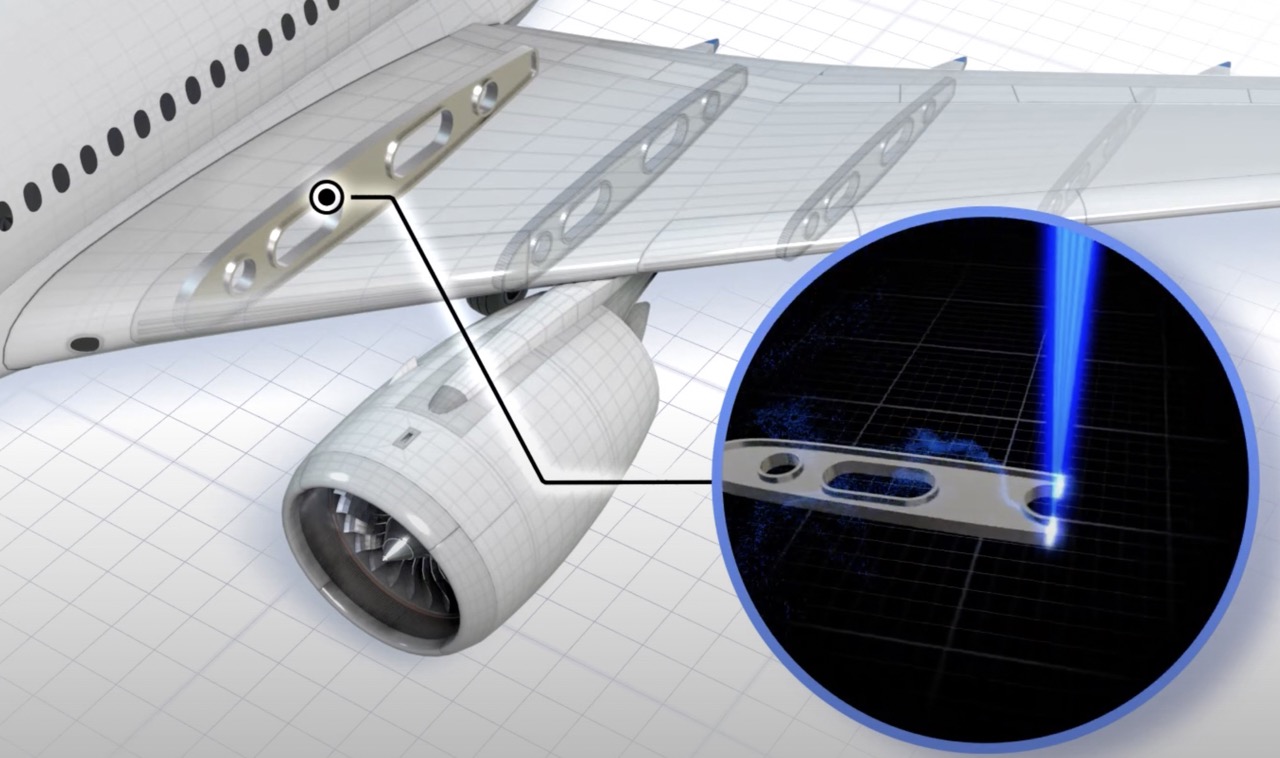
    Additionally, the BL-1000-F’s impact extends to the metal additive 3D printing industry. With its ability to process reflective metals effectively, this blue laser technology opens up new avenues for printing intricate and high-quality metal parts. Manufacturers can achieve greater accuracy, faster printing speeds, and improved overall process stability, revolutionizing the way metal components are produced in various sectors.

    Unveiling at Laser World of Photonics: NUBURU will officially unveil the BL-500-F and the BL-1000-F at the prestigious Laser World of Photonics event in Munich on June 27, 2023. Visitors can explore these groundbreaking technologies firsthand at booth A2 103 (Laser 2000). This event marks a significant milestone in the advancement of blue laser technology and demonstrates NUBURU’s commitment to driving innovation in the manufacturing industry.

    With the introduction of the NUBURU BL-1000-F, the manufacturing landscape is set to undergo a transformative shift. This cutting-edge blue laser technology unlocks new possibilities for EV battery production, metal additive 3D printing, and consumer electronics manufacturing. The BL-1000-F’s higher power, speed, and precision will empower businesses to achieve greater efficiency, superior weld quality, and improved overall manufacturing capabilities. Stay tuned for more updates on NUBURU’s breakthrough solutions and their impact on the industry.

  • Wire-Fed Electron Beam Directed Energy Deposition: Process, Applications and Limits

    Wire-Fed Electron Beam Directed Energy Deposition: Process, Applications and Limits

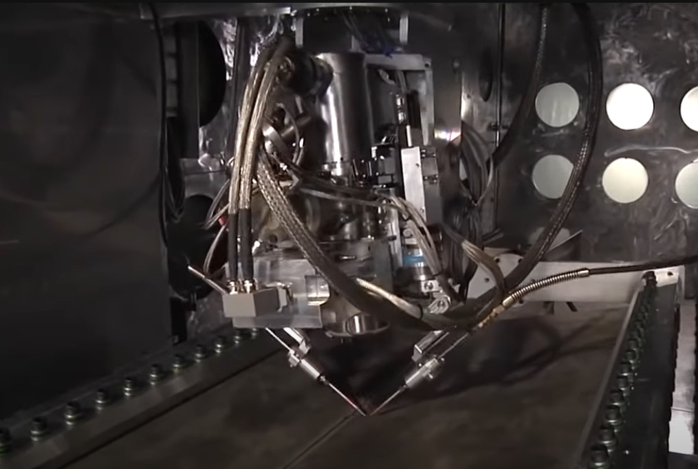
    Wire-fed electron beam additive manufacturing is a directed energy deposition process in which an electron beam creates a melt pool and metallic wire is fed directly into it. The standardized process description is DED-EB/M using wire feedstock. “EBAM” is also widely used, but it is a trademarked commercial term associated with Sciaky.

    This is not electron beam powder bed fusion. Wire-fed DED-EB is built for large near-net shapes, repair and high deposition rates—not fine powder-bed resolution.

    How wire-fed DED-EB works

    1. Digital process planning: A CAD model is converted into deposition paths, layer strategy, machine motion and wire-feed instructions.
    2. Substrate preparation: The build plate, preform or repair component is cleaned, positioned and qualified for deposition.
    3. Vacuum generation: The work chamber is evacuated to permit stable electron-beam operation and reduce oxidation of reactive alloys.
    4. Melt-pool creation: The focused electron beam melts a controlled area of the substrate or previous layer.
    5. Wire deposition: Wire enters the melt pool while the beam, part or deposition head follows the programmed path.
    6. Layer or bead stacking: Beads are overlapped to create walls, features or large near-net preforms.
    7. Monitoring and correction: Beam power, wire feed, travel speed and melt-pool condition may be monitored and adjusted by the machine control system.
    8. Post-processing: The deposited shape is heat treated, inspected and machined to final geometry as required.

    Process classification

    ASTM F3187 defines directed energy deposition as a process in which focused thermal energy fuses material as it is being deposited. DED can use laser, electron-beam or arc energy and can use wire or powder feedstock. Wire-fed electron-beam systems are one branch of this larger process family.

    ProcessEnergy sourceTypical feedstockEnvironmentBest-known use
    DED-EB/MElectron beamWireVacuumLarge near-net preforms in high-value reactive metals
    DED-LB/MLaserPowder or wireInert shielding or controlled enclosureRepair, coatings, features and multi-axis deposition
    DED-Arc/MArc plasmaWireShielding gas or local enclosureLarge structures and high-rate deposition
    PBF-EB/MElectron beamPowder bedVacuumComplex smaller parts, implants and selected aerospace hardware

    Why wire feedstock matters

    Wire is generally easier to handle than fine reactive powder and can provide high material-delivery rates. It is available in established welding-alloy specifications for many metals, although AM production still requires control of chemistry, diameter, cleanliness, cast, helix, spool identity and storage.

    Wire-fed deposition converts stock directly into a near-net shape, but it does not eliminate waste. Start/stop regions, run-on and run-off features, machining allowance, rejected builds and removed substrate material remain part of the yield calculation.

    Main advantages

    High deposition rate

    Commercial systems can deposit several kilograms per hour, with rate strongly dependent on alloy, geometry, quality requirements and machine configuration. Gross deposition rate should not be confused with finished-part throughput. Vacuum cycle, cooling, inspection, heat treatment and machining can dominate total lead time.

    Large build envelope

    DED-EB can produce structures far larger than typical powder-bed machines. The practical limit is set by chamber size, motion system, thermal control, wire access and the ability to machine and inspect the deposited shape.

    High-value material savings

    The strongest economic case often occurs when a large titanium, nickel, tantalum or other expensive-alloy part would otherwise be machined from a very large forging or billet. A near-net DED preform can reduce buy-to-fly ratio and shorten raw-material lead time.

    Repair and feature addition

    Because feedstock is delivered into a local melt pool, DED can add material to existing components or preforms. Repair acceptance requires a defined damage-removal route, substrate condition, interface design, heat treatment and inspection plan.

    Main limitations

    • Low geometric resolution: Bead width and layer height are much larger than powder-bed features.
    • Machining dependency: Critical surfaces, datums, holes and interfaces are normally finish machined.
    • Thermal distortion: Large heat input and long deposition paths can cause warping and residual stress.
    • Bead stability: Wire position, transfer behavior, melt-pool size and path transitions affect consistency.
    • Vacuum infrastructure: Chamber size, pump-down time, seals and maintenance affect cost and availability.
    • Limited access: The beam and wire must reach the deposition location without collision or shadowing.
    • Qualification burden: Large components are expensive to test destructively and difficult to inspect volumetrically.
    • Microstructure variation: Thermal history can vary across thick intersections, starts, stops and long builds.

    Design for wire-fed DED-EB

    • Design near-net, not net-shape. Define machining allowance from process capability and distortion evidence.
    • Use accessible geometry. Ensure the beam, wire and motion system can reach each feature.
    • Control section transitions. Abrupt mass changes create thermal accumulation and path-planning difficulty.
    • Plan deposition sequence. Bead order, direction and dwell time influence distortion and microstructure.
    • Create machining datums. Include robust features for setup, probing and final coordinate transfer.
    • Include run-on and run-off strategy. Starts and stops may require sacrificial material.
    • Design for inspection. Avoid large uninspectable volumes unless process evidence and risk analysis justify them.
    • Consider hybrid substrates. Deposit only where AM creates value and retain forged, plate or machined material elsewhere.

    ISO/ASTM 52922, a design standard for metal DED, was still under development in 2026. ASTM F3413 provides existing design guidance for DED and should be interpreted together with application-specific engineering requirements.

    Materials

    Wire-fed DED-EB is especially attractive for reactive or high-value alloys that benefit from vacuum processing:

    • Titanium and titanium alloys
    • Nickel-based superalloys
    • Tantalum, niobium and selected refractory metals
    • Selected steels and other weldable alloys

    Weldability is a useful starting point but is not sufficient. The route must control dilution, segregation, solidification cracking, phase transformation, chemistry pickup and heat-treatment response.

    Multi-wire and graded materials

    Some systems can use dual wire feeds to increase deposition or vary chemistry. This creates potential for graded composition and custom alloy development, but it also introduces major control questions:

    • How are the two feed rates calibrated and synchronized?
    • Is mixing within the melt pool uniform and repeatable?
    • Can local chemistry be verified throughout the part?
    • Do intermediate compositions form brittle phases?
    • How will the material be specified, heat treated and qualified?

    Multi-material capability should therefore be treated as a material-development program, not a routine printer option.

    Process monitoring and control

    Key variables include beam power, focus, travel speed, wire-feed rate, wire position, melt-pool geometry, layer height and machine motion. Commercial platforms may use cameras or thermal sensing to adjust deposition conditions.

    Closed-loop control can reduce variation, but it does not automatically prove internal quality. Sensor calibration, latency, field of view, data retention and correlation with physical defects remain essential.

    Typical imperfections

    Imperfection or conditionPotential contributors
    Lack of fusionLow energy, poor bead overlap, wire misalignment or contaminated interface
    PorosityWire condition, unstable transfer, entrapped gas or melt-pool turbulence
    CrackingAlloy susceptibility, thermal gradient, restraint and composition changes
    Bead-shape variationWire feed, beam power, travel speed, surface condition and local heat buildup
    DistortionDeposition sequence, substrate restraint, heat input and cooling
    Interface defectsOxide, contamination, insufficient dilution or inadequate surface preparation
    Chemistry variationEvaporation, feedstock variation, cross-contamination or multi-wire imbalance

    ASTM work on a standardized DED imperfection classification was still underway in 2026. Until acceptance frameworks mature, the inspection plan should be based on credible process-specific failure modes and representative demonstration hardware.

    Post-processing and inspection

    • Stress relief, solution treatment, aging or HIP as required
    • Removal from the substrate or retention as a hybrid component
    • Rough and finish machining
    • Surface finishing and cleaning
    • Dimensional inspection
    • Surface and volumetric NDT selected for geometry and defect orientation
    • Material testing from qualified witness locations

    Very large parts can exceed practical CT capacity. Ultrasonic, radiographic, surface and local destructive methods may need to be combined with process qualification and monitoring.

    Applications

    • Aerospace structures: large titanium preforms, tanks, frames and structural features
    • Defense: low-volume, long-lead, high-value metal hardware
    • Energy: large nickel, refractory or specialized-alloy components
    • Repair and remanufacturing: restoration or addition of high-value features
    • Material development: controlled composition experiments using multiple wires

    Economics

    The economic comparison should be against the complete conventional route, often a large forging plus extensive machining. Include:

    • Wire and substrate cost
    • Vacuum and deposition cycle
    • Engineering and path development
    • Build failures and qualification hardware
    • Heat treatment and HIP
    • Machining time and removed material
    • Inspection and documentation
    • Raw-material and tooling lead-time reduction

    DED-EB is strongest where the alternative has a very high buy-to-fly ratio, long forging lead time, low production volume and expensive alloy. It is weak for small precision components that can be produced efficiently by powder bed, casting or machining.

    Selection checklist

    1. Is the part large enough and valuable enough to justify DED?
    2. Can the geometry be created as accessible overlapping beads?
    3. Is suitable wire available with controlled quality and supply?
    4. Can the deposited material be heat treated and qualified?
    5. Is sufficient machining stock included?
    6. Can the complete volume and interfaces be inspected?
    7. Does the facility have vacuum, handling and safety capability?
    8. Does accepted-part cost beat forging, fabrication or alternative DED routes?

    Conclusion

    Wire-fed electron beam DED is a high-rate near-net-shape process for large, high-value metal components. Its advantage comes from combining vacuum processing, wire feedstock and large-scale deposition. Its limitations—coarse geometry, thermal management, machining and qualification—must be included from the first design decision.

    Related Addithive resources: Electron Beam Powder Bed Fusion · Wire Arc Additive Manufacturing

    References and further reading

  • Binder Jetting: Process, Materials, Economics and Industry Platforms

    Binder Jetting: Process, Materials, Economics and Industry Platforms

    Binder jetting selectively deposits a liquid binder onto a powder bed to create a “green” part. The printing step is relatively fast and does not use a laser to melt each voxel. But for metal and many ceramic applications, printing is only the beginning: curing, depowdering, debinding and sintering determine the final geometry and properties.

    The central binder-jetting challenge is not print speed. It is controlling the complete print-to-sinter route with acceptable shrinkage, distortion, density and yield.

    How binder jetting works

    1. A recoater spreads a controlled layer of powder.
    2. An inkjet printhead selectively deposits binder according to the sliced geometry.
    3. The build platform moves and the process repeats.
    4. The powder bed is cured or dried to provide handling strength.
    5. Green parts are removed from the surrounding powder and cleaned.
    6. For metal or ceramic routes, the binder is removed and the part is sintered.
    7. Finishing, heat treatment, machining and inspection are applied as required.

    Sand molds and cores follow a different downstream route: the printed sand tool is cleaned and used directly in a casting process rather than sintered into a dense metal component.

    Schematic of the binder jetting process

    Three distinct binder-jetting markets

    ApplicationPrinted materialWhat the printed object becomesMain value driver
    Metal binder jettingMetal powder plus binderA sintered metal componentBatch productivity, geometry, use of powder-metallurgy feedstocks
    Sand binder jettingFoundry sand plus binderA mold or core for castingToolless complex casting geometry and short lead time
    Ceramic binder jettingCeramic powder plus binderA fired or sintered ceramic componentMaterial flexibility and complex refractory or technical-ceramic shapes

    Why metal binder jetting is attractive

    • High packing density: parts can often be nested in three dimensions because attached thermal supports are not required during printing.
    • Area-wide deposition: print time is less sensitive to the number of individual parts than point-scanning laser processes.
    • Powder-metallurgy compatibility: many systems use powders and sintering knowledge related to MIM or conventional powder metallurgy.
    • Lower thermal stress during printing: the green part is not locally melted by a high-energy beam.
    • Potential production economics: the process can be competitive for suitable small-to-medium parts when printing, furnace loading and yield are balanced.

    These advantages are conditional. If depowdering is difficult, green parts break, sintering distorts the geometry or furnace capacity is constrained, the apparent print-speed advantage disappears.

    The manufacturing bottlenecks

    Green-part strength

    Freshly printed parts are fragile. Binder saturation, drying, powder packing and geometry determine whether a component survives excavation, cleaning and transfer. Thin walls, long unsupported features and handling points need special attention.

    Depowdering

    Internal channels and densely nested builds can trap powder. The design must provide access for gravity, air, vibration, vacuum or automated cleaning. Powder removal must not damage green surfaces or contaminate subsequent batches.

    Debinding

    Binder removal must avoid cracking, blistering or carbon contamination. Thick sections and nonuniform geometry can produce internal pressure or differential debinding rates. The binder chemistry, heating cycle and atmosphere form part of the qualified process.

    Sintering shrinkage

    Metal binder-jetted parts shrink substantially as porosity is removed during sintering. The design is scaled before printing, but shrinkage is not always perfectly uniform. Geometry, powder packing, gravity, friction with setters, furnace temperature uniformity and local section thickness all influence final dimensions.

    Distortion and support in the furnace

    A part may print without supports yet still require setters, sintering supports or sacrificial features. At high temperature the component can creep under its own weight. Unsupported spans, asymmetric mass and thin walls are vulnerable.

    Furnace capacity

    The printer can produce green parts faster than downstream furnaces can process them. Furnace cycle time, usable hot-zone volume, atmosphere, loading strategy and material changeover often determine plant throughput.

    Design for metal binder jetting

    • Use wall thicknesses and aspect ratios demonstrated for the specific powder and process.
    • Avoid large abrupt changes in section thickness that debind and sinter at different rates.
    • Provide powder-removal access to internal volumes.
    • Use generous radii and smooth transitions to reduce stress concentration during handling and sintering.
    • Orient broad surfaces and long spans to minimize gravity-driven distortion.
    • Plan setters or sintering supports before freezing the geometry.
    • Add machining stock to precision interfaces.
    • Separate cosmetic, dimensional and structural requirements by surface.
    • Design witness features or coupons when they provide meaningful process evidence.

    Material properties: compare the qualified route

    Density, strength, ductility, fatigue and corrosion performance depend on powder chemistry, particle-size distribution, binder, printing parameters, debinding, sintering atmosphere and thermal cycle. Published “fully dense” claims should be reviewed with the actual density method, test orientation, specimen geometry and material condition.

    Metal binder jetting can produce strong and useful components, but it should not be assumed equivalent to wrought, MIM or LPBF material without application-specific data. Fatigue-sensitive and safety-critical uses require particular attention to residual porosity, inclusions, surface condition and dimensional variation.

    Binder jetting versus LPBF

    FactorMetal binder jettingMetal LPBF
    During printingBinder joins powder; no local meltingLaser creates a local melt pool
    Thermal supportsNot attached during printingOften required for anchoring and heat transfer
    Primary thermal challengeDebinding and sintering shrinkage/distortionResidual stress, distortion and cracking during/after build
    Part nestingThree-dimensional nesting can be possibleUsually arranged from the build plate with support constraints
    Surface/detailProcess and powder dependent; sintering affects final geometryGenerally finer control for qualified compact features, but downskin remains challenging
    Post-processingCure, depowder, debind, sinter; machining/finishing as requiredDepowder, stress relief, cut-off, support removal; machining/finishing as required
    Strongest economic caseBatch production of suitable sinterable geometriesHigh-value complex parts, internal channels and qualified performance

    Current industrial platform landscape

    The supplier landscape has consolidated and evolved since the early binder-jetting boom. Product names and corporate ownership should be checked at the time of procurement. As of 2026, notable active examples include:

    • Desktop Metal: the X-Series family includes InnoventX, X25Pro and X160Pro for metals, ceramics and composites; the Shop System targets batch metal production. ExOne technology and sand systems are presented within the broader Desktop Metal portfolio.
    • HP: the Metal Jet S100 platform is offered in development and production configurations, with expanded materials and powder-management options announced in 2026.
    • voxeljet: continues to offer large-format binder-jet systems for sand molds, cores and other powder materials.
    • Ricoh: continues development of aluminum metal binder jetting, with emphasis on thermal applications and industrialization.

    A machine list is not a technology assessment. Buyers should evaluate local service, installed-base experience, material availability, furnace integration, application references, software, yield and long-term support.

    Questions to ask before selecting a binder-jet route

    1. What is the complete print, cure, depowder, debind and sinter cycle for this material?
    2. What shrinkage and dimensional capability have been demonstrated on comparable geometries?
    3. Which features require setters, sintering supports or machining?
    4. What green-part breakage and sintering scrap rates are typical?
    5. What limits furnace loading density and cycle time?
    6. How are powder batches, binder condition and reused powder controlled?
    7. Which material properties are based on production-representative parts rather than ideal test coupons?
    8. How is residual powder verified in internal channels?
    9. What is the inspection plan for porosity, distortion and critical dimensions?
    10. What is the cost per accepted part at the target annual volume?

    Standards direction

    ISO/ASTM is developing a dedicated binder-jetting design guideline for single-alloy metal parts using multi-step binder jetting. The work reflects the need to standardize design principles around green-part behavior, depowdering, debinding and sintering rather than treating binder jetting as a simple support-free printing process.

    Conclusion

    Binder jetting is a compelling production route when part geometry, batch density and sintering behavior align. Its economics cannot be judged from printer speed alone. The winning production system balances print capacity with depowdering, green-part handling, furnace throughput, dimensional compensation, finishing and quality assurance.

    Related Addithive resources: Binder Jetting Breakthroughs · Metal AM Process Selection

    References and further reading

  • 3D Printing Stocks in 2023 — Archived Investment List

    3D Printing Stocks in 2023 — Archived Investment List

    This 2023 stock list is no longer a current investment universe

    This article originally reviewed a group of additive manufacturing and 3D-printing stocks using information available in April 2023. It is now preserved as a historical market snapshot.

    Several companies in the original list were acquired, taken private, delisted, restructured or materially changed their additive-manufacturing exposure. The original descriptions and ticker references should not be used for current investment decisions.

    Examples of changes since publication

    Company from the original articleMaterial change after the 2023 snapshot
    SLM SolutionsNikon completed the squeeze-out and made Nikon SLM Solutions a wholly owned subsidiary in 2023; it is no longer a standalone public AM stock.
    Fathom Digital ManufacturingCORE Industrial Partners completed a take-private acquisition in 2024.
    Desktop MetalNano Dimension completed the acquisition in April 2025. Nano Dimension later reported Desktop Metal in discontinued operations following bankruptcy and deconsolidation.
    MarkforgedNano Dimension completed the acquisition in April 2025 and announced an agreement in May 2026 to sell Markforged to Stratasys.
    Nano DimensionThe company’s investment case and AM asset structure changed substantially through acquisitions, divestiture plans and a proposed strategic combination.

    These examples are sufficient to make the original static list unsuitable as an evergreen investment guide. Current research must start from today’s ownership, listing, segment reporting and financial statements.

    Why “3D-printing stock” is an imprecise category

    The original article mixed several fundamentally different exposures:

    • Pure-play printer and materials companies
    • Digital manufacturing marketplaces and service bureaus
    • Software companies with limited AM revenue exposure
    • Diversified industrial companies with small AM divisions
    • Acquired companies that no longer trade independently
    • Companies whose primary value proposition changed after publication

    A better investment universe separates companies by business model, AM revenue exposure, value-chain role and ownership of an industrial bottleneck.

    The current Addithive classification

    BucketWhat it capturesPrimary investor question
    Core or pure-play AMCompanies whose economics depend heavily on additive manufacturingCan the platform reach durable margins and repeat production?
    Equipment and process platformsPrinter, deposition and production-system providersIs installed-base growth converting into recurring revenue?
    Materials and feedstockPowder, wire, polymer, resin and specialty-material suppliersDoes qualification create pricing power or switching cost?
    Software, simulation and digital threadDesign, build preparation, MES, monitoring and quality toolsHow material is AM to the wider software business?
    Services and digital manufacturingContract production and manufacturing marketplacesCan the business generate attractive utilization and gross margins?
    Post-processing and qualityHeat treatment, HIP, machining, metrology and inspectionDoes the company own a constraint that grows with AM adoption?
    Industrial adoptersAerospace, medical, dental, energy and automotive usersDoes AM create product or cost advantage large enough to affect earnings?

    What investors should verify now

    1. Current listing and ownership: Confirm ticker, exchange, parent company and transaction status.
    2. AM revenue exposure: Separate real AM sales from a broad advanced-manufacturing narrative.
    3. Revenue quality: Distinguish equipment shipments, services, consumables, software and recurring revenue.
    4. Installed-base economics: Measure utilization, service attachment and material pull-through.
    5. Cash and dilution: Review burn rate, financing needs and share issuance.
    6. Customer evidence: Look for qualified production and repeat orders rather than demonstrations.
    7. Gross margin and scale: Test whether growth improves economics or increases operating losses.
    8. Bottleneck ownership: Identify whether the company controls software, feedstock, post-processing, qualification or another scarce capability.
    9. Transaction risk: Account for acquisitions, asset sales, strategic reviews and delisting risk.
    10. Valuation: A useful AM technology does not automatically make an attractive stock.

    Current Addithive research

    Primary transaction references

    Archive status: This URL is retained for historical reference and existing external links. It is not investment advice or a current stock list.

  • Desktop Metal and TriTech Titanium Parts Bring Titanium Alloy Ti64 to Binder Jet 3D Printing on the Production System™

    Desktop Metal and TriTech Titanium Parts Bring Titanium Alloy Ti64 to Binder Jet 3D Printing on the Production System™

    TriTech Titanium Parts LLC, a Detroit-based manufacturer of titanium parts for aerospace, marine, and automotive industries, and Desktop Metal, Inc., a global leader in additive manufacturing technologies for mass production, have announced the customer-qualification of Ti64 for binder jet 3D printing on the Production System™. The high-speed Single Pass Jetting (SPJ) technology platform features two models: the P-1, for research and development of binder jetting projects for serial production, and the P-50, the world’s fastest metal binder jet system, offering the lowest cost per part with SPJ technology. Ti64 is a popular material, known for its excellent strength-to-weight ratio, corrosion resistance, and biocompatibility. Binder jetting of Ti64 simplifies the production of complex titanium parts, which can be challenging and expensive to fabricate using traditional manufacturing methods.

    Desktop Metal Production System via Desktop Metal

    TriTech Titanium Parts LLC, which is ISO 9001:2015 certified, uses metal injection molding (MIM), investment casting, and now binder jet 3D printing on the Desktop Metal Production System P-1 to produce titanium parts. The company is a spin-off of AmeriTi Manufacturing Co., which was founded in 1984 and sold last year to Kymera International.

    TriTech’s owner, Robert Swenson, who is also the former owner of AmeriTi, stated that with binder jet 3D printing, titanium production of even the most complex geometries can be greatly simplified and achieved at a lower cost. Swenson, a graduate of Purdue University with a degree in Metallurgical Engineering and an MBA from Harvard Business School, is incredibly proud to be the first Desktop Metal Production System P-1 customer worldwide to binder jet 3D print titanium, and the company is excited to offer this new manufacturing technology to its customers.

    With the latest addition to the material portfolio, Desktop Metal offers the ability to binder jet 23 metals, including copper, aluminum, and now, titanium. Ric Fulop, Founder and CEO of Desktop Metal, stated that they are excited to help engineers and manufacturers produce complex, once-impossible designs in a wide range of metals, including challenging materials such as titanium.

    While Ti64 is a popular material, it’s also known for being expensive to manufacture. The material’s strength, as well as its low thermal conductivity and ductility, make it challenging to machine or produce with traditional manufacturing methods. Shaping the material with MIM requires special knowledge and processes. TriTech is among a very small percentage of companies that produce titanium parts with MIM, and the company has developed its own MIM processes after years of R&D. However, with binder jetting, the process can be simplified and made more economical.

    Binder jetting is a process where an industrial printhead selectively deposits a binder into a bed of Ti64 powder particles, creating a solid part one thin layer at a time, just like printing on sheets of paper. The form or shape produced by the printer is then sintered to high density and accuracy in a furnace, similar to the MIM process. Additionally, binder jetting allows unbound material to be reused in the process, adding to its cost efficiency.

    Desktop Metal’s binder jet technology can 3D print almost any powder, which is why the company has a tiered material qualification system for metals to signify the varying levels of material property results produced by. Production System users interested in working with titanium should consult their Desktop Metal sales representative on hardware and binder requirements.

    TriTech will discuss its experience binder jetting Ti64 at AMUG 2023, held March 19-23 in Chicago. The topic will be part of a Desktop Metal panel discussion from 1:30-2:30 p.m. Thursday, March 23,

  • Unlocking the Potential of Metal 3D Printing: Challenges and Opportunities in the Mobility Industry

    Unlocking the Potential of Metal 3D Printing: Challenges and Opportunities in the Mobility Industry

    Metal additive manufacturing (MAM), also known as “metal 3D printing,” has been around for over 30 years. In the past decade, however, there has been a surge of interest in the technology as it moves from prototype to low-rate and high-rate production for increasingly critical applications for more industries. With this shift comes the challenge of determining design properties for the first time in many years. Not only is it necessary to determine basic material properties, but it is also necessary to accommodate new geometries and design concepts as well. While some of the methods and approaches are common to other product forms, others are unique to MAM.

    MAM is a process that uses a laser or electron beam to melt metal powder and create complex, three-dimensional parts directly from a computer-aided design (CAD) model. The process offers several advantages over traditional manufacturing methods, including the ability to create complex geometries with less waste, shorter lead times, and lower tooling costs. However, as the technology has matured and gained wider acceptance, the need to determine design properties has become increasingly important.

    Additive manufacturing” by oakridgelabnews is licensed under CC BY 2.0.

    One of the main challenges in determining design properties for MAM is the lack of standardized testing methods. While traditional manufacturing methods such as casting, forging, and machining have established testing methods, MAM is still in the process of developing these methods. The lack of standards can make it difficult to compare results between different MAM processes and materials.

    Another challenge is the need to understand the microstructure of MAM parts. The microstructure refers to the arrangement of the atoms in the metal and can have a significant impact on the properties of the part. The microstructure of MAM parts is often different from that of parts made using traditional methods, which can make it difficult to predict the properties of the part.

    To overcome these challenges, product teams must take a methodical approach to determining design properties for MAM parts. This involves understanding the process parameters, material properties, and part geometry, and using this information to develop testing methods that can accurately predict the performance of the part.

    One approach to understanding the process parameters is to use a design of experiments (DOE) approach. DOE involves systematically varying the process parameters and measuring the resulting properties of the part. This can help identify the optimal process parameters for a given material and part geometry.

    Another approach is to develop a process map for the MAM process. A process map is a graphical representation of the process parameters and their impact on the part properties. This can help identify the key process parameters that have the most significant impact on the part properties.

    Understanding the material properties is also critical in determining design properties for MAM parts. This involves characterizing the mechanical, thermal, and chemical properties of the material. Traditional testing methods such as tensile testing, hardness testing, and impact testing can be used to determine these properties.

    In addition to the traditional testing methods, there are also some unique testing methods that are specific to MAM. One such method is the use of computed tomography (CT) scanning to analyze the internal structure of the part. This can help identify defects such as voids, cracks, and inclusions that can affect the part properties.

    Another unique testing method is the use of digital image correlation (DIC) to analyze the deformation of the part under load. DIC involves analyzing images of the part before and after loading to determine the displacement and strain of the part. This can help identify areas of the part that are experiencing high stress and may be prone to failure.

    Once the process parameters and material properties have been characterized, the next step is to determine the part geometry. This involves analyzing the CAD model and identifying areas of the part that may be prone to failure. Finite element analysis (FEA) is a common tool used to simulate the behavior of the part under different loads and boundary conditions. This can help identify areas of the part that are experiencing high stress and may be prone to failure.

    FEA can also be used to optimize the part geometry for the MAM process. This involves modifying the CAD model to minimize distortion, reduce residual stress, and improve the part properties. One approach to this is topology optimization, which involves using algorithms to generate an optimal shape for the part based on a set of design constraints.

    Once the testing methods have been developed and the part geometry has been optimized, the next step is to validate the design properties. This involves testing the part under real-world conditions to confirm that it meets the design requirements. This can include testing the part under different loads, temperatures, and environmental conditions.

    One example of MAM in the mobility industry is the use of the technology to produce lightweight, complex parts for aerospace applications. MAM has been used to produce parts such as brackets, hinges, and latches that are up to 60% lighter than their traditionally manufactured counterparts. These parts offer significant weight savings, which can lead to improved fuel efficiency and reduced emissions.

    To ensure that these parts meet the stringent safety requirements of the aerospace industry, product teams have had to develop new testing methods and standards. For example, the Federal Aviation Administration (FAA) has developed a set of guidelines for qualifying MAM parts for use in aircraft. These guidelines include requirements for material properties, process parameters, and testing methods.

    Looking to the future, there are several areas where further research is needed to fully realize the potential of MAM in the mobility industry. One area is the development of new materials that are specifically designed for the MAM process. These materials could offer improved properties over traditional materials and enable the production of parts with even greater complexity.

    Another area is the development of in-process monitoring and control systems for the MAM process. These systems could help identify defects and deviations in real-time, allowing for immediate corrective action. This could help improve the quality and consistency of MAM parts and reduce the need for post-processing.

    In conclusion, determining design properties for metal additive manufacturing in the mobility industry is a complex and challenging task. However, with the right approach and testing methods, it is possible to develop parts that meet the stringent requirements of the industry. As MAM continues to mature and gain wider acceptance, it will become increasingly important for product teams to understand the unique challenges and opportunities presented by this technology. By doing so, they can unlock the full potential of MAM to produce lightweight, complex parts that offer significant benefits in terms of cost, lead time, and performance.