Tag: material properties

  • Material Advancements: Enhancing 3D Printing Capabilities in Manufacturing

    Material Advancements: Enhancing 3D Printing Capabilities in Manufacturing

    When it comes to advanced manufacturing, additive manufacturing, or 3D printing, has been hailed as a game-changer, capable of revolutionizing various industries. This innovative technology has the potential to unleash an array of new possibilities, from creating complex hollow structures to optimizing part designs for enhanced performance. However, despite its promise, 3D printing has yet to reach its full potential, primarily due to the limitations in materials, cost, and scalability. In this blog post, we will delve into the challenges holding 3D printing back and explore the advancements required to overcome these obstacles.

    The Power of Additive Manufacturing:

    3D printing has opened doors to designs that were once deemed impossible, thanks to its ability to create intricate hollow structures. Designers can now integrate cooling channels directly into high-temperature parts such as turbine blades and rocket nozzles. Additionally, topology optimization allows for the generation of the perfect structure for any application, much like our hollow bones, enabling lightweight vehicles to gain even more performance.

    Furthermore, traditional manufacturing methods often involve machining parts from large blocks of raw materials, resulting in significant waste. In the aviation industry, this waste is measured by the buy-to-fly ratio, which compares the weight of the final part to the weight of the raw material it was manufactured from. With 3D printing, this waste can be significantly reduced, leading to decreased costs and a more sustainable manufacturing process.

    A prime example of the capabilities of 3D printing is the incredible aerospike rocket engine, which incorporates liquid cooling channels directly into the rocket nozzle’s interior. This optimized design results in a highly efficient rocket nozzle that can operate effectively at various altitudes.

    Additive Rocket Engine – NASA

    Challenges and Limitations

    Despite the numerous benefits and potential applications of 3D printing, several factors are holding it back from widespread adoption. One major issue is the cost. When plotting the price of a 3D printed part as a function of the number of parts created, it becomes apparent that the initial machine cost dominates the price, and scaling up requires the purchase of additional machines. This lack of economies of scale makes 3D printing less attractive for high-volume, low-cost applications.

    Another challenge lies in the material properties of 3D printed parts. With thousands of years of experience in traditional metal forging, we have developed a deep understanding of how manufacturing techniques affect a metal’s properties. However, additive manufacturing forces us to start from scratch, building up our knowledge of the material properties of 3D printed parts.

    A key area of research in this regard is improving the fatigue life of 3D printed metals. Fatigue life refers to the number of stress cycles a part can withstand before breaking. Compared to traditionally machined parts, 3D printed parts tend to have a shorter fatigue life, making them less suitable for critical applications such as aviation.

    3D Printed Turbine Blades with Cooling Channels – ORNL

    Research and Advancements in Additive Manufacturing Materials

    Alloy Development for Additive Manufacturing

    Researchers are working on developing new metal alloys specifically designed for additive manufacturing. These alloys aim to provide better material properties, such as improved strength, ductility, and fatigue life, compared to existing materials used in 3D printing. Companies like OXMET are focusing on creating novel metal alloys that are optimized for additive manufacturing, taking into account the unique challenges and opportunities of the technology.

    Researchers at HRL Laboratories have developed a new metal alloy specifically designed for 3D printing: a high-strength aluminum alloy called Al 6061. This material offers improved performance and reduced cracking compared to conventional aluminum alloys. Its successful development and implementation have opened up new possibilities for 3D printed aerospace, automotive, and structural components.

    GRCOP-84 Powder Development – NASA Glenn Research Center

    Post-processing Techniques

    Post-processing techniques, such as hot isostatic pressing, can help improve the fatigue life of 3D printed parts. These methods involve applying heat and pressure to the printed part, closing the pores and imperfections that can lead to crack growth and fatigue failure. Researchers are also exploring other post-processing methods, such as heat treatments, that could further enhance the material properties of 3D printed metals.

    Tailoring Laser Scan Strategies

    By adjusting the laser scan strategy during the 3D printing process, researchers have discovered that they can influence the internal grain structure of the printed metal. This, in turn, affects the material’s properties, such as strength and fatigue life. Different scan strategies, such as the island or helical patterns, are being investigated to optimize the material properties of 3D printed metals.

    One notable example of this research is a project undertaken by the Oak Ridge National Laboratory, where scientists are investigating how adjusting the laser’s speed and power can impact the material properties of 3D printed metals. Their findings could lead to the development of new techniques that improve the fatigue life of printed parts, making them suitable for more demanding applications such as aviation.

    Machine Learning and In-situ Monitoring

    Researchers are also exploring the use of machine learning and in-situ monitoring to optimize the 3D printing process. By using thermal cameras and other specialized sensors inside the build chamber, they can observe phenomena like pore formation and adjust the laser’s operation in real-time to maximize material properties. This approach has the potential to significantly improve the fatigue life and overall performance of 3D printed parts.

    Researchers at the Technical University of Munich have developed a method called “in-situ process monitoring” that uses high-speed cameras to observe and analyze the 3D printing process in real-time. This method helps identify and minimize imperfections, such as porosity or cracks, and optimize the internal crystal grain structures for improved material properties.

    Siemens has been working on a project that combines machine learning and 3D printing to optimize the laser scan strategies for additive manufacturing. By analyzing the data generated during the 3D printing process, the company’s machine learning algorithms can determine the optimal scan patterns and laser settings, resulting in parts with improved material properties and reduced defects.

    Multi-Material Printing and Hybrid Manufacturing

    The future of additive manufacturing will likely involve the ability to print with multiple materials simultaneously, opening up new possibilities for creating complex, multi-functional parts. Hybrid manufacturing, which combines additive manufacturing with traditional subtractive methods like CNC machining, is also an exciting development on the horizon. This approach offers the best of both worlds, enabling the creation of intricate, optimized designs through 3D printing while ensuring the final parts meet the highest standards of precision and surface finish.

    Conclusion

    While 3D printing may not be suitable for low-cost, high-volume parts, improving fatigue life and material properties could lead to its use in more specialized applications, such as aerospace and other high-performance industries. As research continues to optimize 3D printing techniques and materials, we can expect to see additive manufacturing play an increasingly important role in the future of manufacturing.

    The ongoing advancements in cost reduction and material property optimization are creating exciting opportunities for 3D printing. As the technology matures, we may soon see a shift from its current focus on prototyping to a more widespread use in various industries. From automotive to aerospace, 3D printing has the potential to revolutionize how we design and manufacture products. With continued research and innovation, the future of 3D printing looks incredibly promising, and it will undoubtedly continue to shape the manufacturing landscape for years to come.
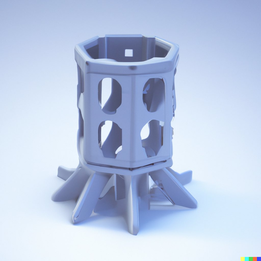
  • Complex Parts in Additive Manufacturing: When Complexity Creates Value—and Risk

    Complex Parts in Additive Manufacturing: When Complexity Creates Value—and Risk

    Additive manufacturing can produce geometry that is difficult or impossible to make with conventional processes. But geometric complexity is not automatically valuable. Every internal channel, lattice, consolidated interface and unsupported feature can add design, build, cleaning, inspection, repair and qualification burden.

    Complexity is not free. AM changes where complexity is paid for—from shape-specific tooling into software, process control, post-processing and verification.

    The three types of complexity

    Complexity typeExamplesPotential valueTypical risk
    Geometric complexityInternal channels, lattices, undercuts, curved passages and topology-optimized shapesPerformance or weight improvementSupports, powder removal, distortion and inspection
    Functional complexityHeat exchange, fluid mixing, energy absorption, sensing or multiple functions in one bodyHigher system performanceHarder validation and coupled failure modes
    Organizational complexityMore software, suppliers, process steps, data and approvalsDigital flexibility and supply-chain redesignChange control, traceability and capability gaps

    A successful AM design reduces total system complexity even when the printed geometry becomes more complex.

    When complexity creates real value

    Internal flow and thermal geometry

    Conformal cooling channels, compact heat exchangers, fuel passages and mixing structures can create performance that drilled holes, brazed plates or cast cores cannot easily match. These are strong AM candidates when the internal surfaces can be cleaned, tested and manufactured repeatably.

    Part consolidation

    Combining several components can remove fasteners, welds, seals, inventory and assembly steps. Consolidation is valuable when it reduces system-level failure modes or cost. It is weak when it creates one expensive, unrepairable component from several simple serviceable parts.

    Topology optimization and lightweighting

    AM can place material along load paths and remove low-value mass. The resulting organic geometry can improve weight-sensitive systems, but it must preserve manufacturing access, minimum feature capability, fatigue performance and inspection.

    Lattices and cellular structures

    Lattices can provide stiffness-to-weight, energy absorption, thermal area, permeability or bone-ingrowth behavior. Their value depends on cell size, strut capability, surface condition, orientation and the ability to verify the internal structure.

    Mass customization

    Patient-matched medical devices, dental products, wearables and personalized tooling can vary geometry without new hard tooling. The manufacturing system must constrain customization within approved design rules.

    The complexity cost stack

    StageHow complexity adds cost
    DesignComputational geometry, optimization, simulation and more design iterations
    Data preparationLarge files, difficult meshes, orientation and support strategy
    PrintingLonger exposure paths, thermal accumulation, fragile features and higher failure consequence
    Material removalTrapped powder, resin, binder or support material
    Post-processingHard-to-reach supports, surfaces, heat-treatment distortion and special fixtures
    MachiningDifficult datums, limited tool access and interrupted cuts
    InspectionCT, advanced metrology, sectioning or indirect evidence
    QualificationMore worst-case locations, coupled features and process sensitivity
    ProductionLower yield and greater loss when one feature fails
    ServiceRepair, cleaning, maintenance and replacement of consolidated hardware

    Printability is only the first gate

    A part can be printable and still be unsuitable for production. A production-ready complex part must pass five gates:

    1. Buildable: It can be produced without unacceptable supports, collapse, distortion or thermal failure.
    2. Cleanable: Powder, resin, binder, support and processing debris can be removed.
    3. Finishable: Required surfaces can be machined, polished, coated or otherwise completed.
    4. Inspectable: Critical dimensions and defects can be verified with adequate probability of detection.
    5. Serviceable: The part can be assembled, maintained, repaired or economically replaced.

    Internal channels: the hidden challenge

    Internal channels are one of AM’s most valuable capabilities and one of its largest industrial risks. Review:

    • Minimum hydraulic diameter and aspect ratio
    • Self-supporting cross-section or internal supports
    • Powder or resin escape paths
    • Line-of-sight for cleaning or finishing
    • As-built roughness and pressure loss
    • Dimensional measurement method
    • Detection of blockage, lack of fusion or thin walls
    • Leak and pressure-test strategy
    • Repair or disposition if a channel fails inspection

    A channel should not be added merely because the printer can create it. It should provide enough thermal, fluid or assembly value to justify its lifecycle controls.

    Supports: geometry’s temporary tooling

    AM is often described as tool-free, but support structures can function as single-use tooling. They can:

    • Anchor the part
    • Conduct heat
    • Resist distortion
    • Support overhangs
    • Protect delicate features

    They also add material, build time, removal labor, surface damage and access requirements. Design complexity that demands inaccessible supports may be economically worse than a simpler conventionally manufactured geometry.

    Inspection is a design input

    NIST identifies complex surface topography, lattices, internal geometry, anisotropic properties and internal defects as major measurement and qualification challenges for AM. Inspection should therefore be selected while the geometry is still being designed.

    FeaturePossible inspection approachLimitation
    External geometryCMM, optical scanning or structured lightLine-of-sight and reflective or rough surfaces
    Internal channelsIndustrial CT, borescope, flow or pressure testPart size, material density and resolution
    Internal defectsCT, radiography or ultrasonic methodsDefect orientation, thickness and geometry
    Surface-connected defectsVisual, penetrant or magnetic methods where applicableRough surfaces can reduce sensitivity
    Lattice structureCT, mass, flow and representative destructive testingLarge data volume and limited access
    Material conditionWitness coupons, hardness, microscopy and mechanical testingCoupon may not represent every complex feature

    Read Addithive’s NDT guide.

    Part consolidation: calculate the net effect

    Before consolidating an assembly, compare both sides:

    Potential gainPotential loss
    Fewer joints and leak pathsOne defect can scrap the complete part
    Lower assembly laborMore expensive inspection
    Lower inventory and supplier countReduced second-source flexibility
    Lower mass and envelopeMore difficult repair or replacement
    Improved flow or thermal performanceInternal surfaces can be inaccessible
    Fewer tolerance stack-upsOne large complex tolerance problem

    The best consolidated designs remove weak interfaces while preserving serviceability and verification.

    Complexity and production yield

    Complex features can increase the probability that at least one requirement fails. If a part contains several independent high-risk features, overall yield can fall rapidly even when each feature has a high individual success rate.

    For example, if five critical features each have a 98% chance of passing and their outcomes are independent, the theoretical probability that all five pass is approximately 90%. Real failure modes are often correlated, but the example illustrates why complexity must be linked to production data.

    • Track yield by feature and location.
    • Identify the feature driving scrap.
    • Separate design failure from process instability.
    • Use representative production nesting.
    • Include downstream machining and inspection yield.
    • Redesign features that consume disproportionate qualification cost.

    A complexity-value scorecard

    Score each dimension from 0 to 5 before committing to AM:

    Dimension05
    Performance valueNo measurable benefitMajor system-level improvement
    Tooling avoidanceExisting tooling is efficientTooling is prohibitive or impossible
    Part consolidationNo useful reductionRemoves major assembly and failure modes
    Material efficiencyConventional route already efficientVery high-value material or buy-to-fly saving
    Production volume fitFar above AM capacityIdeal low-volume or customized demand
    Post-process accessibilitySupports and surfaces inaccessibleAll operations straightforward
    InspectabilityCritical features cannot be verifiedClear validated inspection route
    Qualification maturityNew material and process development requiredQualified route and relevant data exist
    RepairabilityFailure requires total expensive replacementService and disposition are manageable
    Accepted-part economicsClearly unfavorableStrong advantage at realistic yield

    A high geometric-complexity score is not a reason to print. Strong candidates score high on value, accessibility, inspectability and economics at the same time.

    Red flags in complex AM design

    • The geometry was made complex because AM allows it, not because the product needs it.
    • Internal supports cannot be removed.
    • Powder, resin or debris can become trapped.
    • No credible inspection method exists for a critical feature.
    • A lattice is specified without validated process-specific properties.
    • Topology optimization ignores machining and datum strategy.
    • Part consolidation removes replaceable wear components.
    • The design depends on nominal printer resolution rather than demonstrated capability.
    • A failed small feature scraps a large high-value build.
    • Qualification coupons do not represent the critical geometry.
    • The business case excludes CT, support removal or finishing.
    • The design cannot be transferred to another machine or supplier.

    Design review checklist

    1. What measurable system value does each complex feature create?
    2. Can a simpler geometry deliver most of the value?
    3. Which orientation balances performance, supports, distortion and inspection?
    4. How will material and supports be removed?
    5. Which surfaces require machining or finishing?
    6. How will internal dimensions and defects be verified?
    7. Which feature controls first-pass yield?
    8. Does consolidation improve or reduce serviceability?
    9. Does the qualification plan represent the worst-case geometry?
    10. Does the accepted-part economics model include every complexity cost?

    Conclusion

    Additive manufacturing changes the economics of geometric complexity, but it does not eliminate complexity cost. The best AM parts use difficult geometry to reduce total system mass, assembly, tooling or performance constraints while remaining buildable, cleanable, finishable, inspectable and serviceable.

    Related Addithive resources: AM vs Conventional Manufacturing · Surface Finishing for Metal AM · Scaling AM Production

    References

  • Unlocking the Potential of Metal 3D Printing: Challenges and Opportunities in the Mobility Industry

    Unlocking the Potential of Metal 3D Printing: Challenges and Opportunities in the Mobility Industry

    Metal additive manufacturing (MAM), also known as “metal 3D printing,” has been around for over 30 years. In the past decade, however, there has been a surge of interest in the technology as it moves from prototype to low-rate and high-rate production for increasingly critical applications for more industries. With this shift comes the challenge of determining design properties for the first time in many years. Not only is it necessary to determine basic material properties, but it is also necessary to accommodate new geometries and design concepts as well. While some of the methods and approaches are common to other product forms, others are unique to MAM.

    MAM is a process that uses a laser or electron beam to melt metal powder and create complex, three-dimensional parts directly from a computer-aided design (CAD) model. The process offers several advantages over traditional manufacturing methods, including the ability to create complex geometries with less waste, shorter lead times, and lower tooling costs. However, as the technology has matured and gained wider acceptance, the need to determine design properties has become increasingly important.

    Additive manufacturing” by oakridgelabnews is licensed under CC BY 2.0.

    One of the main challenges in determining design properties for MAM is the lack of standardized testing methods. While traditional manufacturing methods such as casting, forging, and machining have established testing methods, MAM is still in the process of developing these methods. The lack of standards can make it difficult to compare results between different MAM processes and materials.

    Another challenge is the need to understand the microstructure of MAM parts. The microstructure refers to the arrangement of the atoms in the metal and can have a significant impact on the properties of the part. The microstructure of MAM parts is often different from that of parts made using traditional methods, which can make it difficult to predict the properties of the part.

    To overcome these challenges, product teams must take a methodical approach to determining design properties for MAM parts. This involves understanding the process parameters, material properties, and part geometry, and using this information to develop testing methods that can accurately predict the performance of the part.

    One approach to understanding the process parameters is to use a design of experiments (DOE) approach. DOE involves systematically varying the process parameters and measuring the resulting properties of the part. This can help identify the optimal process parameters for a given material and part geometry.

    Another approach is to develop a process map for the MAM process. A process map is a graphical representation of the process parameters and their impact on the part properties. This can help identify the key process parameters that have the most significant impact on the part properties.

    Understanding the material properties is also critical in determining design properties for MAM parts. This involves characterizing the mechanical, thermal, and chemical properties of the material. Traditional testing methods such as tensile testing, hardness testing, and impact testing can be used to determine these properties.

    In addition to the traditional testing methods, there are also some unique testing methods that are specific to MAM. One such method is the use of computed tomography (CT) scanning to analyze the internal structure of the part. This can help identify defects such as voids, cracks, and inclusions that can affect the part properties.

    Another unique testing method is the use of digital image correlation (DIC) to analyze the deformation of the part under load. DIC involves analyzing images of the part before and after loading to determine the displacement and strain of the part. This can help identify areas of the part that are experiencing high stress and may be prone to failure.

    Once the process parameters and material properties have been characterized, the next step is to determine the part geometry. This involves analyzing the CAD model and identifying areas of the part that may be prone to failure. Finite element analysis (FEA) is a common tool used to simulate the behavior of the part under different loads and boundary conditions. This can help identify areas of the part that are experiencing high stress and may be prone to failure.

    FEA can also be used to optimize the part geometry for the MAM process. This involves modifying the CAD model to minimize distortion, reduce residual stress, and improve the part properties. One approach to this is topology optimization, which involves using algorithms to generate an optimal shape for the part based on a set of design constraints.

    Once the testing methods have been developed and the part geometry has been optimized, the next step is to validate the design properties. This involves testing the part under real-world conditions to confirm that it meets the design requirements. This can include testing the part under different loads, temperatures, and environmental conditions.

    One example of MAM in the mobility industry is the use of the technology to produce lightweight, complex parts for aerospace applications. MAM has been used to produce parts such as brackets, hinges, and latches that are up to 60% lighter than their traditionally manufactured counterparts. These parts offer significant weight savings, which can lead to improved fuel efficiency and reduced emissions.

    To ensure that these parts meet the stringent safety requirements of the aerospace industry, product teams have had to develop new testing methods and standards. For example, the Federal Aviation Administration (FAA) has developed a set of guidelines for qualifying MAM parts for use in aircraft. These guidelines include requirements for material properties, process parameters, and testing methods.

    Looking to the future, there are several areas where further research is needed to fully realize the potential of MAM in the mobility industry. One area is the development of new materials that are specifically designed for the MAM process. These materials could offer improved properties over traditional materials and enable the production of parts with even greater complexity.

    Another area is the development of in-process monitoring and control systems for the MAM process. These systems could help identify defects and deviations in real-time, allowing for immediate corrective action. This could help improve the quality and consistency of MAM parts and reduce the need for post-processing.

    In conclusion, determining design properties for metal additive manufacturing in the mobility industry is a complex and challenging task. However, with the right approach and testing methods, it is possible to develop parts that meet the stringent requirements of the industry. As MAM continues to mature and gain wider acceptance, it will become increasingly important for product teams to understand the unique challenges and opportunities presented by this technology. By doing so, they can unlock the full potential of MAM to produce lightweight, complex parts that offer significant benefits in terms of cost, lead time, and performance.