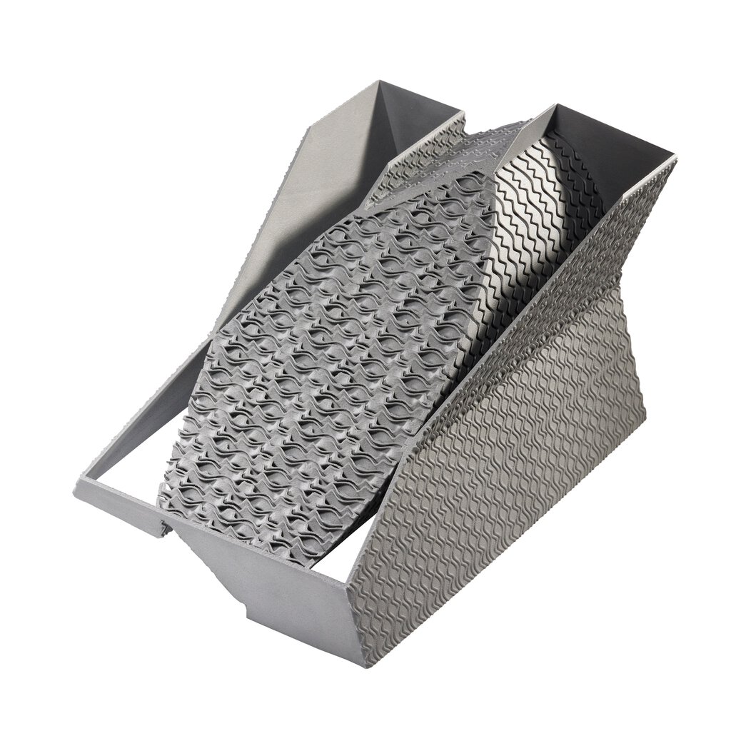
In a groundbreaking collaboration, nTopology, the leading engineering design software developer, and EOS, the industrial 3D printing industry pioneer, have announced a significant breakthrough in additive manufacturing (AM) workflow. The development of a new Implicit Interop capability aims to solve a major bottleneck in the industry by enabling the transfer of highly complex designs in megabyte-sized files, thereby revolutionizing the time to manufacturing.
Industrial heat exchanger printed on EOS M 290 Source: EOS
Traditionally, file sizes for 3D printers could reach tens of gigabytes, posing significant challenges for the manufacturing process. However, nTopology and EOS have now introduced the nTop Implicit File, which can drastically reduce file sizes by up to 99%, generate files 500 times faster, and achieve 60% faster load times. These advancements make the technology more accessible to AM build preparation software, expediting the entire manufacturing workflow.
One of the impressive demonstrations at the Formnext 2022 event in Frankfurt, Germany, featured a large industrial heat exchanger, designed by Siemens Energy as a proof-of-concept. The intricate design, exported to an nTop Implicit File within seconds, required less than 1 MB of storage space. The file was then seamlessly imported into EOSPRINT, where it was used to additively manufacture the heat exchanger using an EOS M 290 industrial 3D printer. This successful application showcased the immense potential of the Implicit Interop technology.
To drive broader adoption of their innovation, nTopology and EOS are collaborating with the 3MF Consortium to standardize the Implicit File format. This collaboration aims to incorporate the technology into a future update of the 3MF industry-standard 3D printing file format, further enhancing compatibility and ease of use across the industry.
Bradley Rothenberg, nTopology Co-founder and CEO, expressed the company’s commitment to empowering engineers with design freedom and enabling the production of complex parts. By working closely with EOS, they developed a solution to address the design data bottlenecks encountered in printing intricate designs. This partnership exemplifies their dedication to advancing the industry and fostering collaborations with original equipment manufacturers (OEMs).
Industrial heat exchanger printed on EOS M 290 Source : EOS
Alexander Bockstaller, Software Product Line Manager at EOS, acknowledged the rising complexity of part geometries due to modern design approaches like topology optimization, generative design, and design for additive manufacturing (DfAM). These advancements have necessitated a solution to handle large and intricate meshes more efficiently. EOS takes up the challenge by driving the standardization of implicit geometry representation, making it possible to build designs that were previously unattainable.
Ole Geisen, Head of Engineering Services for Additive Manufacturing at Siemens Energy, applauded the technical development achieved by nTopology and EOS. He emphasized that the rest of the additive manufacturing ecosystem now needs to catch up with these advancements. As topology optimization, generative design, and DfAM continue to push the boundaries of complexity in part geometries, exchanging such intricate designs using traditional data formats becomes increasingly challenging. The Implicit Interop technology is a game-changer, removing a significant barrier and paving the way for innovation in thermal management and beyond.
The introduction of the Implicit Interop capability by nTopology and EOS marks a pivotal moment in the additive manufacturing industry. This technological breakthrough not only addresses the long-standing bottleneck of handling large file sizes but also unlocks new possibilities for engineers and designers to create complex and innovative products. As the implicit geometry representation becomes standardized, the industry can expect improved interoperability, streamlined workflows, and accelerated adoption of advanced design techniques. With continued collaborations and advancements, the future of additive manufacturing looks promising and full of exciting opportunities.
Vat photopolymerization is an additive manufacturing process in which light selectively cures liquid photopolymer resin inside a vat. It is known for fine detail, smooth surfaces and a broad range of model, dental, medical, tooling and end-use polymer applications.
Vat photopolymerization is the process category. SLA, DLP, MSLA/LCD and continuous-interface methods are different ways of delivering light and separating each cured layer.
How the process works
Model preparation: The part is oriented, supported and sliced according to the printer and resin system.
Resin loading: A compatible liquid photopolymer is placed in the vat or supplied through a controlled cartridge system.
Selective exposure: A laser, projector or masked light source delivers the energy pattern for one layer.
Photopolymerization: Photoinitiators trigger a reaction that converts the exposed liquid into a crosslinked solid.
Layer separation: The platform moves and the cured layer separates from the vat window or free surface so fresh resin can flow into place.
Build repetition: Exposure and platform movement continue until the component is complete.
Washing: Uncured surface resin is removed using the validated cleaning process.
Post-curing: Additional light and sometimes heat complete the material cure and establish final properties.
Support removal and finishing: Supports are removed and critical surfaces are finished or inspected.
SLA, DLP, MSLA and continuous processes
Method
Light delivery
Main characteristic
Important limitation
Laser SLA
A focused laser scans each layer
Flexible spot control and mature professional ecosystem
Exposure time generally scales with the scanned area and path
DLP
A digital projector exposes a complete layer or tiled region
Layer exposure can be rapid and independent of the number of parts in that projected area
Pixel size, projection optics and build-area mapping affect resolution
MSLA/LCD
An LCD mask shapes light from an underlying source
Cost-effective full-layer exposure and widespread desktop use
Optical uniformity, pixel geometry, screen life and thermal management matter
Continuous interface methods
Projected light with a controlled inhibition or separation zone
Reduced discrete peel interruption and potentially rapid production
Process, material and geometry remain platform specific
Industry terminology is not perfectly consistent. Some suppliers use “SLA” broadly for resin printing, while others reserve it for laser-scanning systems. For technical communication, specify the light-delivery method, machine and material.
Top-down vs bottom-up systems
Top-down
The part is cured near the free surface of the resin and moves downward into the vat. Top-down systems can avoid repeated peeling from a transparent vat floor, but usually require a larger resin volume and careful control of the liquid surface.
Bottom-up
The part is cured against a transparent window and lifted away after each layer. Bottom-up systems use less resin and support compact machines, but separation forces can distort parts, damage supports or limit cross-sectional area. Flexible films, low-force release systems and continuous interfaces are different approaches to managing this step.
What determines accuracy and resolution?
Pixel size or laser spot size alone does not determine part accuracy. Relevant factors include:
Optical focus, distortion and intensity uniformity
Resin absorption, photoinitiator response and cure depth
Exposure strategy and overcure beyond the intended boundary
Layer thickness and anti-aliasing method
Temperature and resin viscosity
Platform calibration and vat-window condition
Support stiffness and peel/separation forces
Washing, drying and post-cure shrinkage
Part orientation and geometry
A smaller advertised pixel does not automatically produce a more accurate component. Validate critical features with the actual machine, resin, orientation and post-cure route.
Photopolymer materials
Vat materials are formulated systems containing monomers or oligomers, photoinitiators, stabilizers, pigments and other additives. Common commercial classes include:
Standard model resins: visual prototypes and presentation models
Tough or durable resins: functional prototypes with improved impact or elongation
High-temperature resins: tooling, fixtures and controlled thermal exposure
Flexible and elastomeric resins: seals, cushioning and compliant products
Castable resins: burnout patterns for jewelry and dental casting
Dental and medical resins: validated indications with defined washing, curing and biocompatibility requirements
Ceramic-filled slurries: green shapes that require debinding and sintering
Filled engineering resins: formulations modified with ceramic, glass or other particles
Resin names such as “ABS-like” or “nylon-like” describe behavior, not chemical equivalence. Use technical data from parts produced and post-cured by the specified route.
Post-curing is part of manufacturing
The printed component is usually not in its final material state when it leaves the machine. Post-curing can change:
Tensile strength and modulus
Elongation and impact behavior
Heat-deflection performance
Color and surface condition
Dimensional stability
Biocompatibility status for validated medical materials
Light wavelength, intensity, temperature, time, part spacing and cure-unit condition should follow the material supplier’s validated instructions. Excess or insufficient curing can both create performance problems.
Washing and cleaning
Washing removes uncured resin from the surface and internal features. Isopropyl alcohol is common, but some materials use alternative solvents or aqueous systems. The process must control:
Solvent concentration and contamination
Wash time and agitation
Drainage from channels and cavities
Part swelling or surface attack
Drying before post-curing
Waste handling and solvent recovery
Cross-contamination between material classes
NIOSH research indicates that washing and drying operations can be significant sources of vapor exposure. Post-processing should receive the same ventilation and safety attention as printing.
Health and safety
Uncured photopolymer resin should not be treated as ordinary plastic. Formulations may contain skin irritants or sensitizers, and printing, pouring, washing and curing can create vapor or particle exposure.
Read the resin and solvent safety data sheets.
Prevent skin and eye contact using compatible gloves, eye protection and controlled handling.
Provide ventilation appropriate to resin and solvent use.
Keep resin and contaminated tools away from food and uncontrolled public areas.
Use closed washing and curing equipment where practical.
Cure or dispose of resin, absorbents, filters and solvent according to local requirements.
Control spills and do not wash uncured resin into drains.
Train users in normal operation, maintenance and emergency response.
Personal protective equipment is the last line of defense. Equipment enclosure, ventilation, closed transfer and good work design should reduce exposure first.
Design considerations
Support orientation: place witness marks away from functional or cosmetic surfaces.
Drainage: provide openings for resin and washing fluid to escape from hollow parts.
Peel area: large cross-sections can increase separation forces in bottom-up systems.
Wall thickness: thin walls can distort during printing, washing or curing.
Hole compensation: light bleed and overcure can make small holes undersized.
Machining and assembly: allow stock and robust datum features where precision interfaces are required.
Long-term exposure: validate UV, moisture, chemical and temperature resistance for service.
Common defects and failure modes
Condition
Possible contributors
Delamination or layer separation
Insufficient exposure, contamination, high separation force or poor support
Dimensional overgrowth
Overexposure, light bleed and compensation error
Missing or weak features
Underexposure, poor resin flow, pixel/spot limit or support failure
Warping
Uneven cure, support release, washing, thermal post-cure or residual stress
Surface tackiness
Incomplete washing, oxygen inhibition or insufficient post-cure
Cracking or embrittlement
Material aging, excessive cure, geometry, environment or unsuitable resin selection
Clouding or staining
Contaminated solvent, incomplete drying or cure interaction
Internal uncured resin
Inadequate drainage, washing and access
Applications
Dental: models, surgical guides, denture components, splints and other validated indications
Medical: anatomical models, guides and device components using approved material/process routes
Jewelry: high-detail patterns and castable models
Prototyping: visual, ergonomic and functional design validation
Tooling: molds, inserts, jigs and fixtures within material limits
Consumer products: customized lattices, wearables and low-volume components
Ceramics: printed green bodies followed by debinding and sintering
Claims about aerospace engine hardware, long-term implants or other critical service require specific material, process and regulatory evidence. High visual quality alone does not establish engineering suitability.
Scaling production
Full-layer exposure can provide strong productivity, but industrial output depends on the complete cell:
Resin storage, mixing and identification
Printer and vat availability
Wash-station capacity and solvent management
Drying and post-cure capacity
Support removal and finishing labor
Inspection and traceability
Material shelf life and vat maintenance
Worker exposure and waste controls
Production cost should include resin loss, supports, wash solvent, failed parts, post-cure, labor and quality—not only print time.
How to select a vat-photopolymerization system
Define final mechanical, thermal, optical and regulatory requirements.
Select the material and validated post-cure route before comparing nominal resolution.
Test representative walls, holes, channels, supports and part height.
Measure accuracy after washing and final curing.
Review resin handling, ventilation, wash and waste requirements.
Evaluate open versus closed material ecosystems and change control.
Calculate complete cost per accepted part at the planned product mix.
Confirm software, traceability, service and long-term material availability.
Conclusion
Vat photopolymerization is a broad process family, not a synonym for one printer type. SLA, DLP, MSLA and continuous-interface platforms offer different optical and separation strategies, but all depend on controlled resin chemistry, washing, post-curing, safety and application validation. Select the complete material-process route—not the smallest advertised pixel.