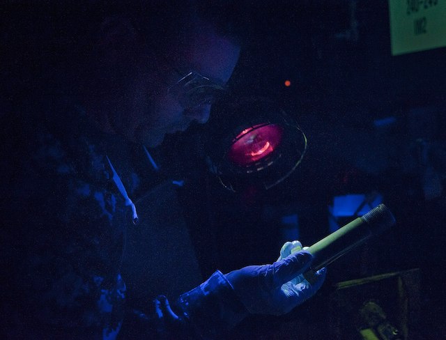
Nondestructive testing (NDT) is essential for additive manufacturing, but no single method can guarantee that a complex AM part is defect-free. Inspection capability depends on the process, alloy, geometry, surface condition, defect type, defect orientation, required resolution and acceptance criteria.
The correct question is not “Which NDT method is best for AM?” It is “Which combination of methods can detect the credible defects in this specific part with the required probability of detection?”
Why AM inspection is different
Metal additive manufacturing can produce internal channels, lattices, thin walls and highly integrated geometries that are difficult to inspect using methods developed for simple wrought or machined parts. AM defects can also be small, irregular, directionally oriented and distributed differently across the build.
Inspection planning therefore begins with the complete manufacturing route: feedstock, machine, process parameters, build orientation, heat treatment, hot isostatic pressing, machining and surface finishing. Post-processing can close, reveal, reshape or remove indications, so the inspection stage matters.
Common defect and imperfection classes
| Imperfection | Typical cause | Inspection challenge |
|---|---|---|
| Lack of fusion | Insufficient energy, poor overlap, contamination or unstable powder layer | Often planar and orientation-sensitive |
| Gas porosity | Entrapped gas, powder condition or melt-pool behavior | Small rounded pores may require high volumetric resolution |
| Keyhole porosity | Excessive energy density and unstable deep melt pool | May appear as irregular or elongated pores |
| Cracks | Residual stress, hot cracking, thermal cycling or alloy sensitivity | Thin planar cracks can be difficult to detect when poorly oriented to the inspection beam |
| Inclusions or contamination | Foreign material, oxide, spatter or handling contamination | Detectability depends on density contrast and size |
| Dimensional deviation | Shrinkage, distortion, support failure, thermal behavior or post-processing | Internal geometry may be inaccessible to conventional metrology |
| Surface-connected discontinuities | Support removal, machining damage, cracking or incomplete fusion | Rough as-built surfaces can create false or masked indications |
| Trapped powder | Insufficient escape paths or ineffective cleaning | May be hidden inside channels and cavities |
X-ray computed tomography
Industrial X-ray computed tomography (CT) is one of the most powerful tools for AM because it can reconstruct internal and external geometry in three dimensions. It can detect porosity, lack-of-fusion regions, inclusions, dimensional deviations, trapped powder and inaccessible internal features.
CT is not unlimited. Detectability depends on voxel size, focal spot, detector, material density, wall thickness, part diameter, scan geometry, reconstruction and analysis settings. A large dense nickel-alloy part cannot be inspected at the same resolution as a small aluminum coupon. CT resolution claims must be connected to the actual part and minimum defect size.
- Strengths: volumetric data, internal geometry, pore distribution and dimensional comparison.
- Limitations: cost, scan time, penetration, artifacts, resolution versus part size and interpretation complexity.
- Best practice: validate the technique using representative artifacts or seeded flaws and document the scan and analysis parameters.
Conventional radiography
Two-dimensional radiography can detect volumetric discontinuities and density variations, but it compresses three-dimensional information into a projection. Overlapping features and complex geometry can mask defects. Planar flaws aligned unfavorably to the beam may be difficult to see.

Ultrasonic testing
Ultrasonic testing can detect internal cracks, lack of fusion and other discontinuities in suitable geometries. Phased-array and advanced full-matrix techniques can improve coverage and imaging. However, rough surfaces, thin sections, complex curvature, internal channels and anisotropic microstructures can complicate coupling, wave propagation and signal interpretation.
Machined inspection surfaces or purpose-designed access may be needed. Calibration blocks and reference reflectors should represent the alloy, heat treatment, geometry and expected defect orientation as closely as practical.

Liquid penetrant testing
Liquid penetrant testing is effective for surface-breaking discontinuities on nonporous, clean surfaces. As-built AM roughness can retain penetrant and generate excessive background. The method is often more reliable after machining or surface finishing, when the inspection surface and cleaning process are controlled.
Penetrant testing cannot detect sealed internal defects and should not be treated as evidence of volumetric integrity.

Magnetic particle testing
Magnetic particle testing can reveal surface and near-surface discontinuities in ferromagnetic alloys. It is not applicable to titanium, aluminum, austenitic stainless steels or most nickel alloys. Surface roughness, geometry and residual magnetism must be controlled.

Eddy current testing
Eddy current methods detect surface and near-surface discontinuities in electrically conductive materials. They can be sensitive to small cracks, but probe access, lift-off, curvature, roughness, conductivity variation and geometry affect performance. Eddy current inspection is generally local rather than a complete volumetric method.

Optical and dimensional inspection
Coordinate measuring machines, structured-light scanners, laser scanners and optical microscopy verify dimensional and surface requirements. They do not replace volumetric NDT. Line-of-sight systems cannot measure hidden channels, and highly reflective or rough surfaces may require preparation or specialized scanning strategies.
In-situ monitoring is not final NDT
Melt-pool sensors, layer imaging, recoater monitoring, acoustic signals and machine logs can identify process anomalies. These data improve traceability and may support adaptive control. However, an anomaly signal is not automatically a verified defect, and the absence of an alarm does not prove that the part is acceptable.
In-situ monitoring must be correlated with destructive testing, NDT and production outcomes before it can support acceptance decisions. It is best viewed as one layer in a broader process-control and inspection strategy.
Probability of detection and validation
A method may detect a large laboratory defect without reliably detecting the smallest critical defect in production. For safety-critical applications, inspection capability should be demonstrated using representative part thickness, geometry, alloy, surface condition and defect type.
- Define the minimum relevant defect size and orientation.
- Use representative reference standards, test artifacts or intentionally seeded flaws.
- Control equipment, calibration, software, analysis thresholds and operator qualification.
- Document false-call risk and inspection blind zones.
- Revalidate the method when geometry, material, surface or equipment changes materially.
How to build an AM inspection plan
- Identify critical functions and credible failure modes.
- Map likely imperfection types to the AM process and post-processing route.
- Define inspection zones and required detection capability.
- Select complementary surface, dimensional and volumetric methods.
- Design inspection access into the part where possible.
- Validate methods on representative artifacts or seeded flaws.
- Set acceptance criteria based on engineering significance, not merely visibility.
- Link results to build records, material genealogy and configuration control.
Quick method comparison
| Method | Best at | Main limitation in AM |
|---|---|---|
| X-ray CT | Internal geometry and volumetric defects | Resolution, penetration, artifacts, cost and part-size trade-off |
| Radiography | Volumetric density changes in suitable geometries | Feature overlap and limited 3D localization |
| Ultrasonic testing | Internal cracks and planar defects with suitable access | Rough surfaces, complex geometry and anisotropic propagation |
| Liquid penetrant | Surface-breaking defects | As-built roughness and no subsurface capability |
| Magnetic particle | Surface/near-surface defects in ferromagnetic materials | Material limitation and surface sensitivity |
| Eddy current | Small surface/near-surface cracks in conductive materials | Local access, lift-off and geometry sensitivity |
| Optical/CMM | External dimensions and visible surface condition | No internal volumetric capability |
| In-situ monitoring | Process anomalies and traceability | Requires correlation; not direct proof of final part integrity |
Conclusion
Reliable AM inspection combines process knowledge, complementary NDT methods and validated detection capability. Complex geometry does not make a part uninspectable by definition, but it can create blind zones that must be understood during design. The inspection plan should be developed with the part and manufacturing route, not added after printing.
Related Addithive research: Aerospace AM Qualification Guide · Design for LPBF
References and further reading
- ISO/ASTM TR 52905:2023 — NDT and defect detection in metal AM parts
- ISO/ASTM 52948:2026 — Classification of powder-bed-fusion imperfections
- ASTM F3704/F3704M-24 — NDT levels and acceptance criteria for laser PBF parts
- ISO/ASTM 52927:2024 — Main AM quality characteristics and test methods
- ISO/ASTM TR 52906:2022 — Intentionally seeded flaws for NDT validation