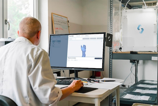
Additive manufacturing technologies are often described by commercial names such as FDM, SLS, SLA, DMLS, PolyJet or WAAM. These names are useful, but they can mix trademarks, historical terms and process physics. A clearer starting point is the seven process categories used by ISO/ASTM terminology.
Choose an additive manufacturing process by how material is delivered, consolidated and supported—not by the popularity of a machine brand.
ISO/ASTM 52900:2021 remains the current confirmed international vocabulary standard for additive manufacturing. It defines AM as creating physical 3D geometry through successive addition of material and organizes the field into standardized process categories.
The seven standard AM process categories
| Process category | How the part is formed | Common feedstock | Typical applications |
|---|---|---|---|
| Vat photopolymerization | Light selectively cures liquid photopolymer in a vat | Photopolymer resin or ceramic-filled slurry | Dental devices, models, patterns and fine polymer parts |
| Material extrusion | Material is selectively dispensed through a nozzle or orifice | Thermoplastic filament, pellets, paste, concrete or bioink | Prototypes, tooling, large-format parts and construction |
| Powder bed fusion | Thermal energy selectively fuses regions of a powder bed | Polymer, metal or selected ceramic powder | Functional polymer parts, metal components and implants |
| Binder jetting | Liquid binder selectively joins particles in a powder bed | Metal, ceramic, sand, gypsum or other particulate material | Sand molds, metal parts, ceramics and visual models |
| Material jetting | Droplets of build material are selectively deposited | Photopolymer, wax, nanoparticle suspension or functional ink | Detailed models, casting patterns and multi-material parts |
| Directed energy deposition | Focused energy melts material as it is deposited | Metal powder or wire | Repair, feature addition and large near-net metal parts |
| Sheet lamination | Sheets are bonded and shaped layer by layer | Paper, polymer, metal foil or composite sheet | Models, embedded structures and selected metal components |
1. Vat photopolymerization
Vat photopolymerization uses light to selectively solidify a liquid resin. The category includes several light-delivery and layer-separation approaches:
- Laser SLA: a focused laser scans the layer.
- DLP: a projector exposes a complete layer or projected region.
- MSLA/LCD: an LCD mask shapes light from an underlying source.
- Continuous-interface methods: reduce discrete peel interruptions through a controlled inhibition or separation zone.
Strengths: fine detail, smooth surfaces, dental and medical material ecosystems, full-layer exposure on projection systems and broad visual-model capability.
Constraints: uncured-resin handling, washing, drying, post-curing, support marks, long-term polymer aging and indication-specific material validation.
Read the detailed vat photopolymerization guide.
2. Material extrusion
Material extrusion selectively dispenses material through a nozzle. The most familiar route melts thermoplastic filament, but the category is much broader.
- Filament extrusion: commonly called FFF; FDM is a Stratasys-associated trademarked term.
- Pellet extrusion: uses polymer granules for higher material flow and large-format systems.
- Paste extrusion: deposits ceramics, food, energetic materials, silicones or other viscous formulations.
- Concrete extrusion: deposits pumpable cementitious material for construction elements.
- Extrusion bioprinting: deposits cell-containing or biomaterial formulations for research.
Strengths: accessible equipment, wide material forms, low feedstock cost, large build sizes and straightforward multi-material concepts.
Constraints: bead-scale resolution, anisotropy, voids, interlayer bonding, warpage, support needs and variable surface quality.
3. Powder bed fusion
Powder bed fusion spreads a layer of powder and selectively fuses regions using thermal energy. The unused powder supports surrounding geometry, although metal systems often still need supports for heat transfer, anchoring and distortion control.
Polymer PBF
Selective laser sintering is widely used for nylon and thermoplastic elastomer components. Other commercial platforms use alternative heating or fusing-agent strategies while remaining within powder-bed-based polymer production concepts.
Laser metal PBF
Laser powder bed fusion of metal is also described by commercial or historical names such as SLM and DMLS. The standardized process description is clearer: PBF-LB/M, powder bed fusion using a laser beam for metallic material.
Electron-beam metal PBF
PBF-EB/M uses an electron beam in vacuum and typically maintains an elevated powder-bed temperature. It is distinct from wire-fed electron-beam directed energy deposition.
Strengths: complex geometry, functional polymer production, dense metal parts, strong aerospace and medical ecosystems.
Constraints: powder safety and genealogy, thermal distortion, supports, surface condition, build size, machine qualification and post-processing.
Related guides: LPBF terminology and electron-beam PBF.
4. Binder jetting
Binder jetting selectively deposits a liquid binder onto a powder bed. The printed object is usually a weak green part or mold that requires additional processing.
- Sand binder jetting: produces molds and cores for metal casting.
- Metal binder jetting: prints a green part followed by depowdering, debinding and sintering.
- Ceramic binder jetting: creates green ceramic shapes requiring thermal processing or infiltration.
- Color model printing: uses colored binder with suitable powder systems for visual models.
Strengths: rapid area-based printing, support-free powder-bed geometry, high nesting density and useful foundry applications.
Constraints: fragile green parts, depowdering, binder removal, furnace capacity, shrinkage, distortion and final density.
Read the binder jetting guide.
5. Material jetting
Material jetting deposits droplets of build material. The deposited material can be cured by light, cooled from a molten state or processed through another consolidation step.
- Photopolymer material jetting: produces detailed multi-material and multi-color polymer models.
- Wax jetting: creates precision casting patterns.
- Nanoparticle or suspension jetting: deposits material-containing droplets followed by drying, curing or sintering.
- Functional ink deposition: overlaps with printed and additively manufactured electronics.
Strengths: fine visual detail, color, controlled droplet placement and multi-material capability.
Constraints: material cost, support removal, UV and thermal aging, nozzle maintenance and limited structural-material options on many platforms.
6. Directed energy deposition
Directed energy deposition delivers material into a focused heat source. Unlike powder bed fusion, feedstock enters only where material is being deposited.
| DED route | Energy source | Feedstock | Typical use |
|---|---|---|---|
| Laser DED | Laser | Powder or wire | Repair, coatings and feature addition |
| Arc DED / WAAM | Electric arc | Wire | Large structures and high-rate near-net deposition |
| Electron-beam DED | Electron beam | Usually wire | Large reactive-metal preforms under vacuum |
Strengths: repair, large build envelope, high deposition rate, hybrid manufacturing and low buy-to-fly potential.
Constraints: coarse feature resolution, thermal distortion, bead stability, substantial machining and difficult inspection of large volumes.
Related guides: wire arc AM and wire-fed electron-beam DED.
7. Sheet lamination
Sheet lamination bonds layers of sheet material and shapes them into the final geometry. Major routes include:
- Laminated object manufacturing: cuts and bonds paper, polymer or composite sheets.
- Ultrasonic additive manufacturing: bonds metal foils using ultrasonic energy, often with intermediate machining.
- Composite sheet lamination: stacks and bonds reinforced sheets or tapes.
Strengths: relatively low thermal exposure in ultrasonic metal routes, embedded sensors or channels, multi-material sheet combinations and rapid model production.
Constraints: interlayer bonding, geometric access, removal of surrounding material, limited adoption and process-specific design rules.
Processes often confused with the seven categories
| Term | How to classify it |
|---|---|
| Hybrid manufacturing | A production system combining AM with machining or another process; the AM step still belongs to one of the seven categories |
| Bioprinting | An application domain using extrusion, material jetting, vat or other deposition principles |
| Construction 3D printing | Usually material extrusion, although printed formwork and metal routes can use other categories |
| Additively manufactured electronics | An application field using material jetting, extrusion, aerosol deposition and hybrid methods |
| Cold spray additive manufacturing | Commonly treated within directed-energy-deposition-related industrial frameworks, although consolidation occurs through high-velocity solid-state impact rather than melting |
| Voxel printing | A design and material-control concept rather than a separate fundamental process category |
| 4D printing | Printed objects designed to change over time under a stimulus; not a separate AM process category |
How to select the right process
- Define the application. Prototype, tool, implant, flight part and visual model require different evidence.
- Start with the material. Confirm that a qualified feedstock and post-processing route exist.
- Set the geometry envelope. Include build size, minimum walls, channels, overhangs and machining access.
- Define property requirements. Strength, fatigue, temperature, chemical resistance and aging may eliminate processes early.
- Map post-processing. Supports, cleaning, heat treatment, HIP, debinding, sintering and finishing can determine feasibility.
- Plan inspection. Complex internal features need credible measurement and defect-detection methods.
- Calculate accepted-part economics. Include yield, labor, furnaces, machining and quality—not only print time.
- Evaluate scale. Determine whether takt time and downstream capacity meet demand.
- Check qualification maturity. Standards, supplier capability and material data vary by process.
- Compare hybrid alternatives. The best solution may print only the difficult feature and use conventional processes elsewhere.
Quick process-selection matrix
| Requirement | Processes commonly considered first |
|---|---|
| Fine polymer detail | Vat photopolymerization or material jetting |
| Durable support-free polymer production | Polymer powder bed fusion |
| Complex dense metal parts | Metal powder bed fusion |
| Large metal near-net shapes | Directed energy deposition |
| High-density metal batch production | Metal binder jetting where sintering and economics are proven |
| Low-cost desktop prototypes | Material extrusion |
| Sand molds and cores | Binder jetting |
| Multi-color visual models | Material jetting or selected binder-jet systems |
| Embedded materials or sensors in metal foil | Ultrasonic sheet lamination |
| Repair or local feature addition | Directed energy deposition |
Conclusion
The additive manufacturing universe is easier to understand when commercial names are mapped to seven standardized process categories. Each category solves a different material-delivery and consolidation problem. Process selection should begin with application requirements and include the complete downstream route, qualification burden and cost per accepted part.
Related Addithive resources: Introduction to Additive Manufacturing · Metal AM Process Selection · History of Additive Manufacturing

